
Configuring Velmex Controls with Additional Components
- Joysticks
- Interface Modules
- Limit Switches
Joysticks for VXM™ Step Motor Controller
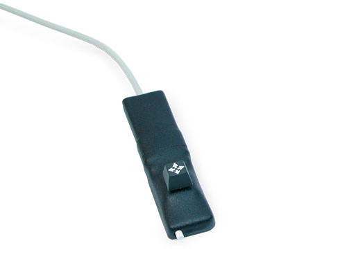
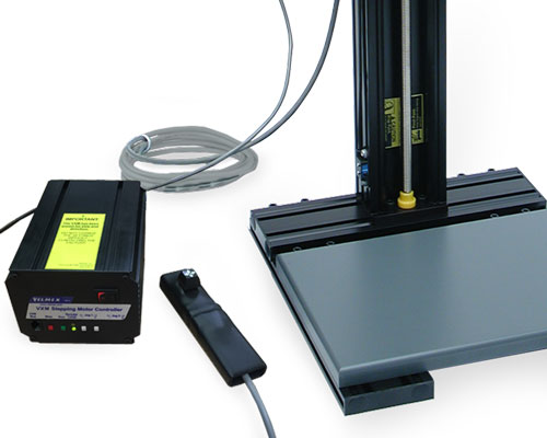
Digital Joystick – allows remote jog control of a one or two axis VXM controller. The palm size hand-held Joystick provides on/off outputs that connect to the Jog Motor inputs on the Auxiliary I/O via an included 10 foot cable. An input switch allows toggling between 2 settable maximum speed values. The Joystick functions like the front panel jog buttons on the VXM: • Momentary = motor moves one step |
 |
 |
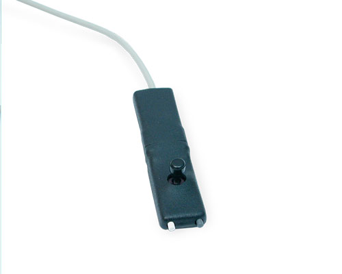
Analog Joystick – derives speed (velocity) and direction from joystick position. Motor velocity is proportional to joystick distance from center and the settable speed ranges. Simultaneous 2-axis motion is accomplished with two VXMs. An input switch allows a single joystick to toggle between 2 motors of a 4 motor system. The Joystick is 1 million cycle design in a convenient hand-held enclosure with a 10 foot cable.
|
 |
 |
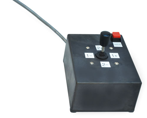
Heavy duty 2-axis Joystick – is a digital joystick that controls two axes. For more robust commercial/industrial applications with a larger desk mount control box. Operational design is similar to the digital joystick.
|
 |
 |
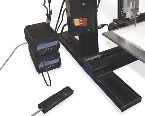
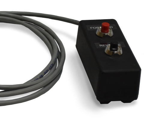
Heavy Duty Remote Jog Station - The Jog Station remotely moves (jogs) a single axis VXM-1 or VXM-1J Controller via push buttons. It offers convenient one-hand operation. Push the button to move in one direction. Release to stop. Push the other button to move in the opposite direction. Release to stop. |
 |
| Type | File Name | Description | View |
|---|---|---|---|
| Analog Joystick.pdf | Instructions - VXM connection and programming information for the analog joystick. | ||
| Digital Joystick.pdf | Instructions - VXM connection and programming information for the digital joystick. |
Interface Modules for VXM™ Step Motor Controller
Interface modules provide additional options for configuring your motorized system with other auxiliary devices.
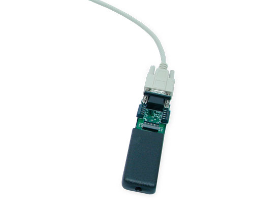
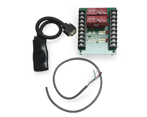
Auxiliary I/O Breakout Module – The I/O Module is a convenient method to interface to the VXM auxiliary I/O, for instance an external stop button.
|
 |
Relay Modules – Allow the VXM to interface with auxiliary devices, such as a camera, to enable them to work in concert with each other. Up to 4 modules are available for the relay board.
|
 |
| Type | File Name | Description | View |
|---|---|---|---|
| I O Breakout Module.pdf | Instructions - VXM connection and programming information for the I/O Breakout Module | ||
| Interfacing to Relay Modules.pdf | Instructions - VXM connection and programming information for Relay Modules |
Limit Switches on Velmex Motorized Linear Stages
Limit Switches are electro-mechanical devices that regulate the motion on positioning devices. On Velmex products they are primarily used to stop/turn off the motor when activated preventing over-travel of the carriage/slider. They also can be used to send an event signal. Limits connect with controllers, such as the Velmex VXM™ Step Motor Controller. Velmex uses several different types.
• Adjustable (moveable) limits, which are standard on BiSlide Assemblies and optional on XSlide and UniSlide Assemblies.
• Fixed end of travel limits, which are standard on XSlide Assemblies and optional on UniSlide Assemblies. These are not adjustable.
• Internal limits which are only available on the UniSlide MB90 Series.
• Home switches, which actually reference a point rather than limit travel, are used on Rotary Tables and can be used on XSlide Assemblies.
It is possible to purchase motor-driven Velmex stages without limits, however, it is not recommended and it may effect the warranty should you incur any damage.
The following at-a-glance chart outlines the Velmex Stage and what limits can be used.
| Available Limit Switches | ||||
|---|---|---|---|---|
| Velmex Product | Adjustable | Fixed, End-of-Travel | Internal | Home Switch |
| BiSlide® Assemblies | Standard | N/A | N/A | Optional* (Mechanical) |
| UniSlide® MA15 Series | Optional | Optional (Outboard) | N/A | Optional* (Mechanical) |
| UniSlide® MA25 Series | Optional | Optional (Outboard) | N/A | Optional* (Mechanical) |
| UniSlide® MA40 Series | Optional | Optional | N/A | Optional* (Mechanical) |
| UniSlide® MA60 Series | Optional | Optional | N/A | Optional* (Mechanical) |
| UniSlide® MB90 Series | Optional | Optional | Standard | Optional* (Mechanical) |
| UniSlide® XY Tables | Optional | Optional | N/A | N/A |
| XSlide™ Assemblies | Optional | Standard | N/A | Optional* (Magnetic) |
| Rotary Tables | N/A | N/A (Can be produced with 2 zero reference home switches) | N/A | Optional (Magnetic) |
*Requires an additional control other than VXM™ Controller
| BiSlide® Limits | ||
|---|---|---|
 |
Adjustable limits (standard) - Velmex BiSlide Assemblies have two adjustable limit switches mounted in a track on the side rib of the assembly to prevent over-travel. An optional third limit switch can be added between the two standard limits and used as an adjustable home switch. (This would require a different controller.) |
|
| UniSlide® Limits | ||
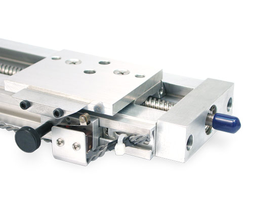 |
Adjustable Limits (Optional) - Mounted on the side rib of Velmex UniSlide Assemblies, these two switches can be used to stop travel. These are ordered as a separate part number (OBLS). |
|
 |
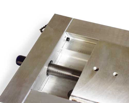
The adjustable limits are located inside a rail that runs the length of the UniSlide® base. A 1/4" cam plate is added to the carriage/slide that depresses the cam when the carriage encounteres it and activates the switch. Thumb locks affix the limit in the proper position. (Pictured: 2 Limits on MA15 Series) |
|
 |
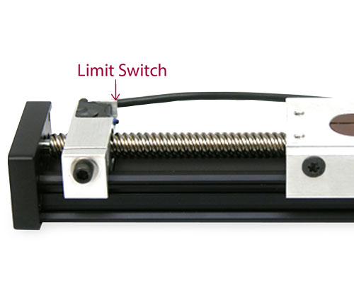
Fixed, End-of-travel Limits (Optional) (MA40, MA60, MB90)- These push button switches are fixed on the side rib of Velmex Unislide Assemblies. They are not adjustable. On all UniSlide Series except the MA15 and MA25 the limits are built into the end plate of the slide. On the MA15 and MA25 Series they are outboard switches affixed to the side rib. These are ordered as a separate part number which begins 3-934. |
|
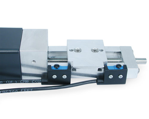 |
Fixed, End-of-travel Limits (Optional) (MA15, MA40) - Outboard fixed, end-of-travel limits available on the MA15 and MA25 UniSlide Assemblies. |
|
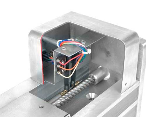 |
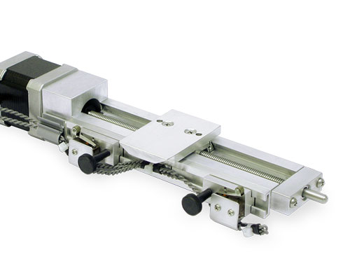
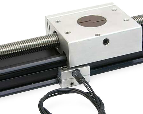
Internal Limits (MB90 "J" Only - Standard) - The internal limits on the MB90 Series consist of two switches, a control rod mounted along side the lead screw with two moveable brass collars and cover atop an additional 3" of dovetail base as shown. The collars are positioned on the control rod to activate the limits. The internal limits on the MA90 Series UniSlide Assembly are referenced by the letter "J" at the end. |
|
| XSlide™ Limits | ||
 |
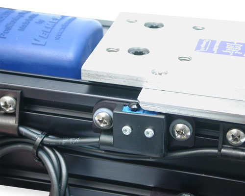
Fixed, End-of-travel Limits (Standard) - XSlide Assemblies have two fixed, end-of-travel limit switches built into the end plates. XSlide fixed limit switches are referenced by either a "-21" or "-71" at the end of the model number. |
|
 |
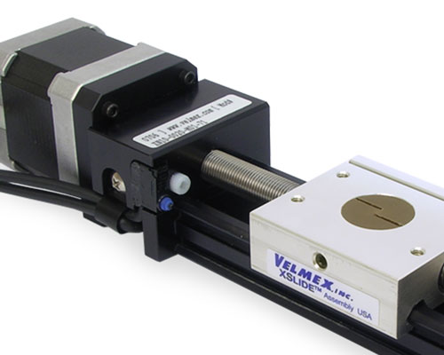
Adjustable Limits (Optional) - Moveable limit switches can be added as an option to motorized XSlide Assemblies. These switches can be used to stop travel within the overall travel distance of the XSlide. When installed the adjustable limits reduce travel distance by 1.2" (3.05 cm). These are ordered as a separate part number (XSW-X-PR). |
|
 |
Magnetic Reed Home Switch (Optional) - A magnetic reed home switch sets a reference point to return the carriage to home (starting) position. This is moveable. Ordered as a separate part number (XSW-M). |
|
| Rotary Table Limits | ||
 |
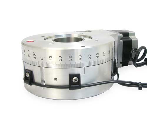
Magnetic Home Switch (Optional) - A magnetic reed home switch sets a reference point to return the carriage to home (starting) position. This is moveable. Ordered as a separate part number (XSW-M). |
|
 |
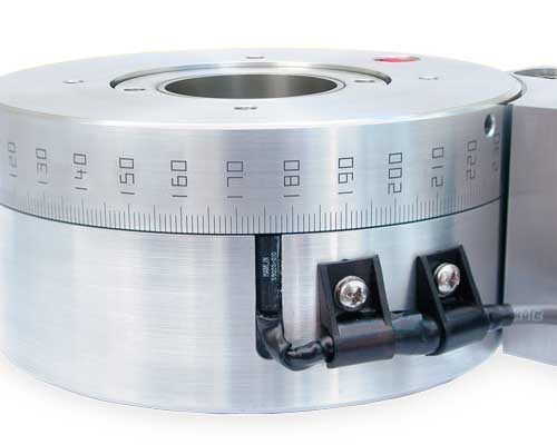
Limit Switches (Optional) - Using two zero-reference (home) switches on a Rotary Table creates limits that restrict travel to a specific degree arc. |
|
Limit Switch Wiring for VXM™ Controller
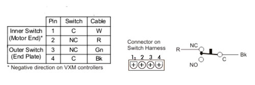
Amp1-480703-0 (mates with:1-480702-0)
*Negative direction on VXM controllers
Connector on Switch Harness are wired on the normally closed (NC) terminals.
CAUTION: The VXM puts 24VDC on the limit switches. Do not connect limit inputs to any +5V logic devices.
Additional information can be found in the VXM™ Users Manual and in the documentation on Limit Switches.
| Type | File Name | Description | View |
|---|---|---|---|
| Limit Switches and VXM.pdf | Instructions - VXM wiring and programming information for limit switches. |