
|
|---|
BiSlide Motorized Linear Stages
Manually-operated BiSlides® can be easily converted to motorized versions. Additionally, Velmex offers motorized Tandem and Belt-drive Assemblies. The T-slot frame system that makes assembling multi-axis positioning systems quick and easy is available for both manually-operated and motorized BiSlides. (Motors are purchased separately. Customers can mount their own motors, if they chose.)
tab=0Overviewtab=1Featurestab=2Model / Seriestab=3Specificationstab=4Options / Accessoriestab=5Downloadstab=6Examplestab=7Troubleshooting / FAQs
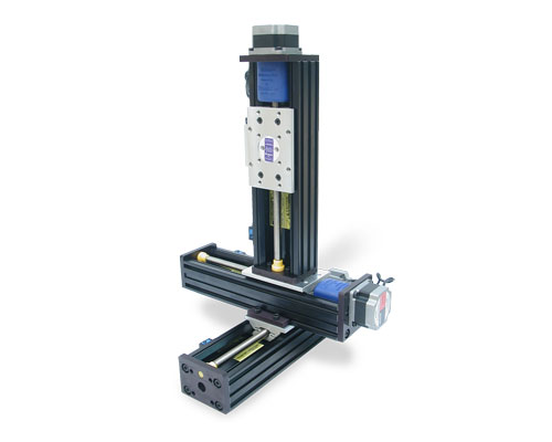
Motor-Driven BiSlide® Assemblies
The Velmex BiSlide positioning stage's modular design makes it highly configurable for a multitude of different motion-control applications. Motorized BiSlide Systems are available in linear models with travel distances up to 228 inches.
Constructed with hard-coat anodized, aluminum dovetail ways and smooth motion PTFE bearings; BiSlides deliver higher rigidity for longer life and more precise movement. BiSlides have a load capacity of 300 lbs. (136 kg.) horizontally and 100 lbs. (45.4 kg.) vertically. Straight-line accuracy is 0.003" (0.076 mm) over entire travel distance. Repeatability is 0.0002 inch (0.005 mm).
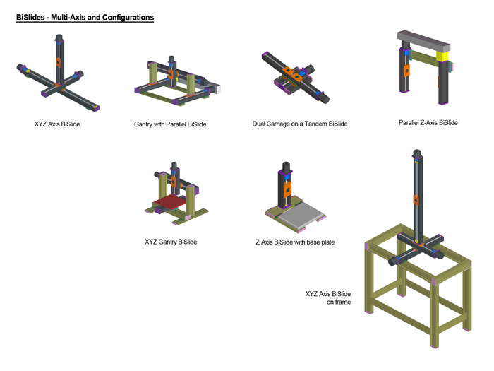
Because BiSlide components are interchangeable, they can easily be reconfigured as the need arises. One, two, three axis systems and more are created by simply bolting together standard components utilizing the advantages of T-slot framing.
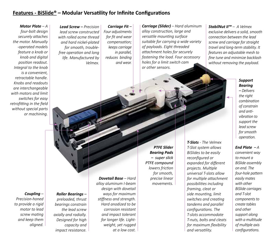
BiSlide® Features
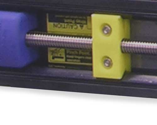 A resonance damper is included on BiSlides over 40" to minimize whip that can develop at higher speeds. The dampers, located some distance apart on either side of the carriage, will move with the carriage when it approaches a damper helping to sustain smooth motion.
I-Beam Framing
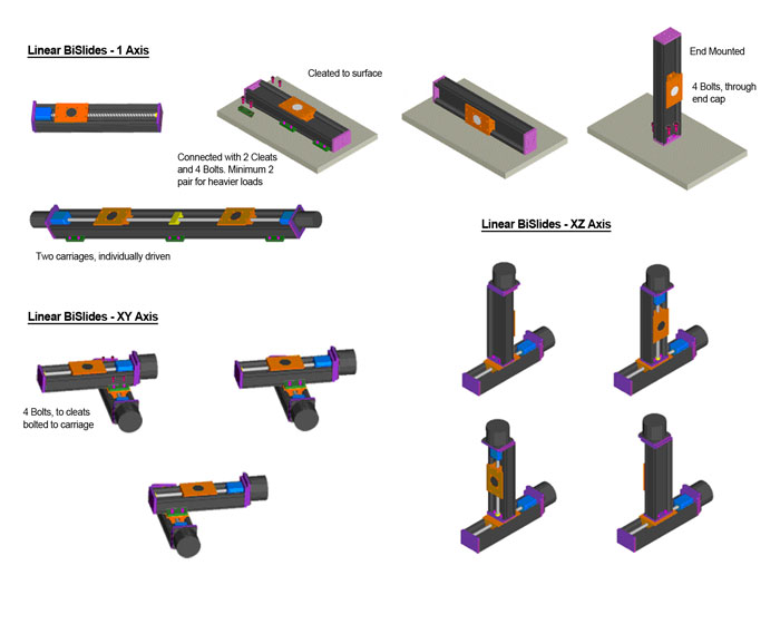
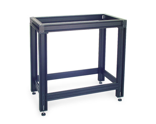 A unique feature of Velmex BiSlides is the number of mounting, framing and structural profiles available. BiSlides can be mounted flat, on edge or on either end. Because of their T-slot base design, they can be mounted to tables, bases, frames and other structures constructed from the same heavy-duty I-beam rails giving heavier loads and longer traverses additional support. Infinite configurations can be created from the versatile system.
Another unique feature of Velmex BiSlide Assemblies is how easily they can be converted from manual to motorized. As noted they can be easily retrofitted in the field without special parts or machining. All that's needed is a manual to motorized conversion kit.
BiSlide Applications
The design is ideal for scientific, medical, industrial, optical, inspection and scanning applications. The systems can be used to position, align, measure, test, fixture and machine, to name a few of the functional uses.
Manufacturers will find the BiSlide system delivers ease of service and upgrade-ability to keep up with rapidly changing marketplaces. Researchers will find BiSlides easy to reconfigure and expand for different projects. Educators will appreciate BiSlide's durable construction, low cost, and easily understood design concepts for demonstrating linear motion principles.
Motor-Driven BiSlide® Series / Style
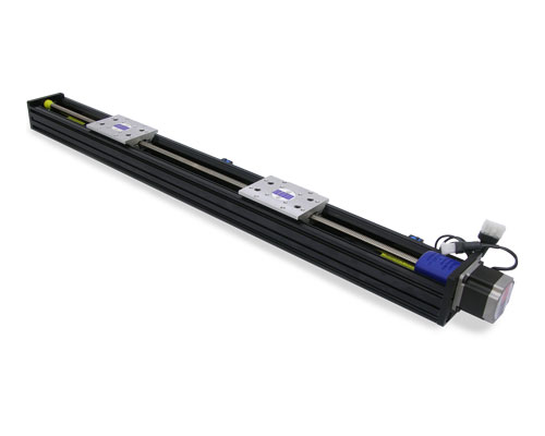
BiSlide Motor-Driven Linear Stages – One axis slides that can be combined for multiple axes in a multitude of travel distances up to 228".
Style Options
Manually-operated BiSlides can easily be retrofitted with motors and limit switches in the field without special parts or machining. Motors can be added to all styles of BiSlides to position the carriage with the exception of the Free Motion BiSlide. BiSlides accommodate NEMA size 23 and 34 motors.
Standard style options for motor-driven BiSlides include:
Part number information for each style can be found under Specifications at the end of the page.
|
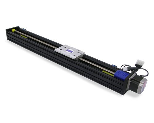
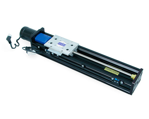
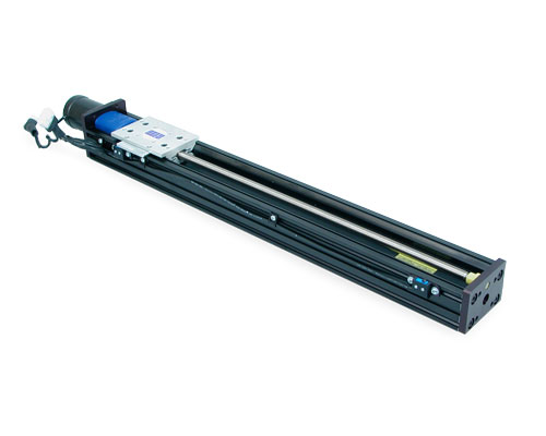
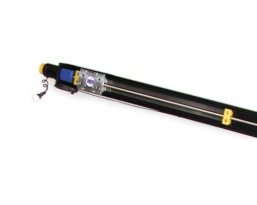
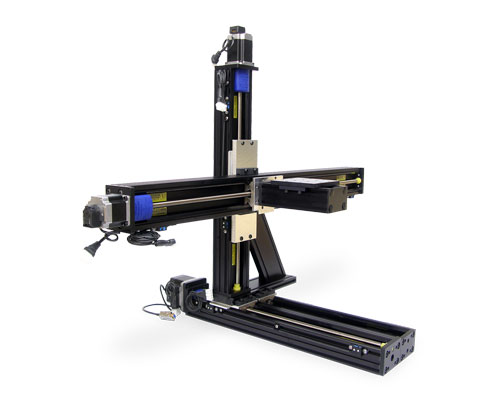
Lead Screw with Limit Switches– A single-axis BiSlide assembly available in several lead screw pitches. The motor to lead screw connection is a precision-honed steel coupling that rigidly clamps to the motor shaft to maintain alignment without the need for key ways or set screw flats. Travel distances to 80 inches (203 cm). |
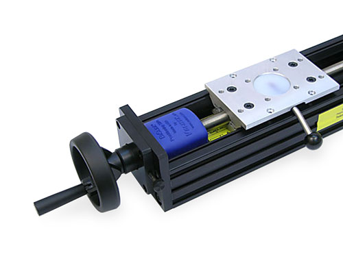 |
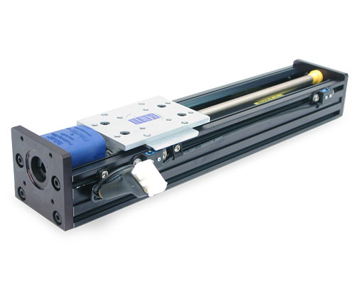
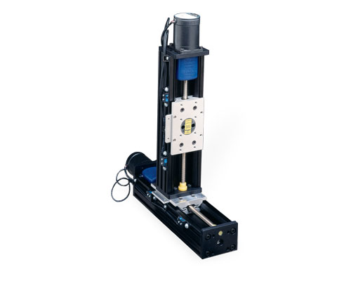
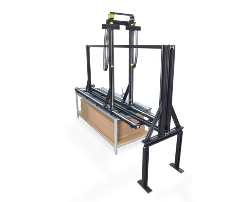
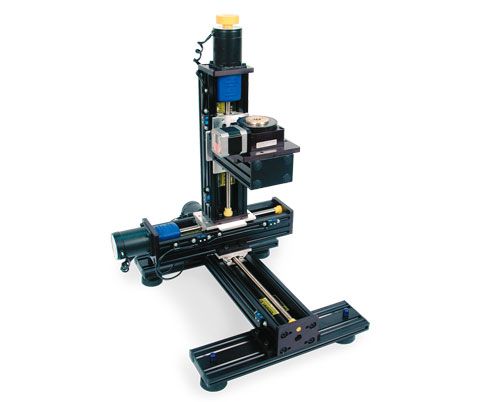
Rapid Advance – The Rapid Advance BiSlide Assembly quickly positions the carriage by hand and fine-tune it with a one step jog using the motor. The Rapid-Advance feature disengages the drive screw so that the carriage can be repositioned. (Pictured is the manual version.) |
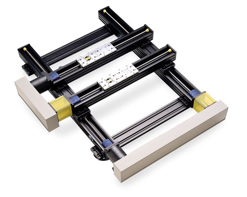 |
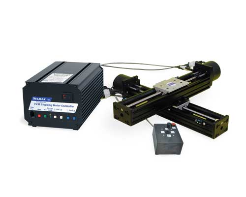
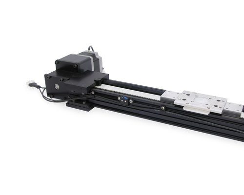
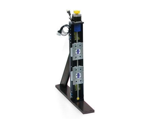
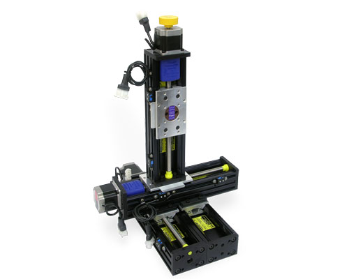
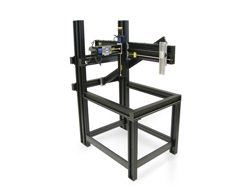
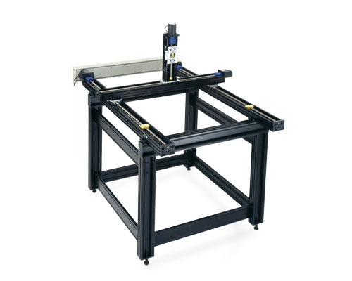
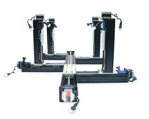
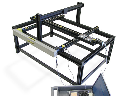
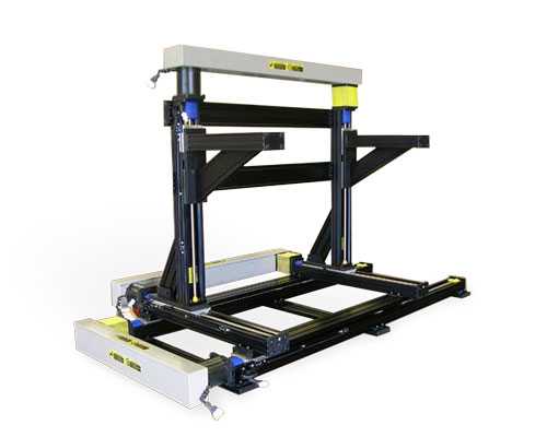
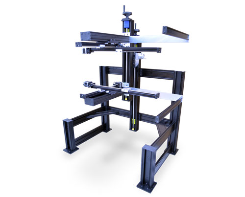
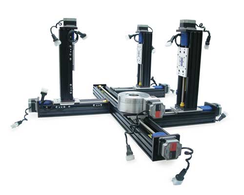
Parallel-Coupled – Two or more identical single-axis BiSlides coupled together to handle larger loads and longer traverses. The operation of the BiSlides are kept in synch through a timing belt. Motor-driven, Parallel-Coupled BiSlide Assemblies can be either lead screw or belt-driven configurations. (Pictured is a system with 2 lead screw Parallel-Coupled BiSlides mounted XY. See the Parallel-Coupled detail page for more information. |
|
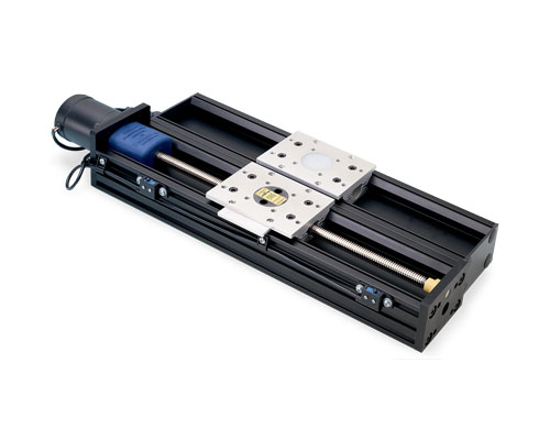
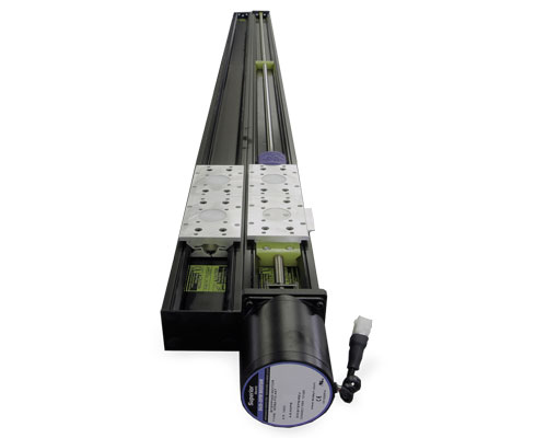
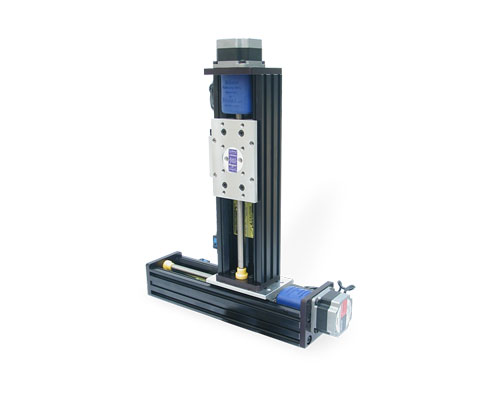
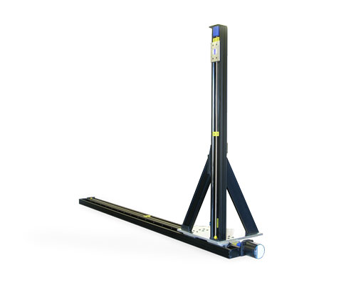
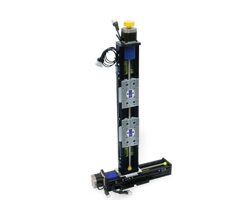
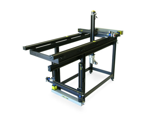
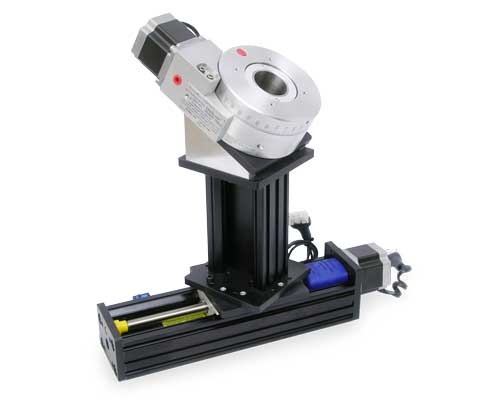
Tandem – A combination of a motor-driven BiSlide and a Free Motion model with the same travel distance mechanically connected so that the carriages operate in tandem. The increased stiffness of this style BiSlide can carry larger loads. |
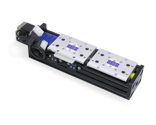 |
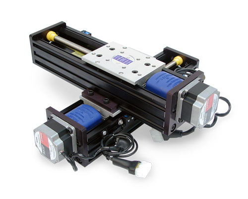
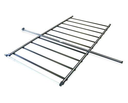
Left-Right Screw Models (LR) – The slides simultaneously move toward or away from each other. Use for applications where two objects must share a common axis of movement.. |
|
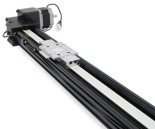
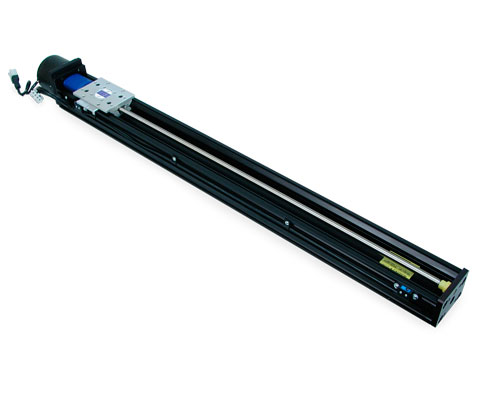
Belt-Drive – This style BiSlide delivers longer travel distances, up to 19 ft. (228 inches/5.8 m) and faster speeds up to 3 meters per second. The high efficiency of the Belt-driven BiSlide make it ideal for moving light loads at high speeds and for continue duty applications. See the Belt-Driven detail page for more information. Please note: While we offer 10" and 20" Belt-driven BiSlides for special applications, travel lengths under 30" are not recommended for practical use for high speed or continuous duty applications. |
Velmex also offers manual BiSlide Assemblies.
BiSlide Special Applications/Configurations
| Velmex has created BiSlide Systems for specific applications. These include: | |
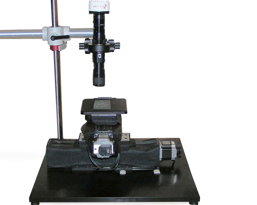 |
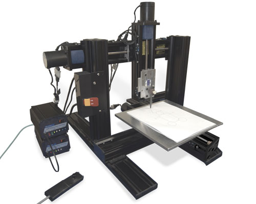
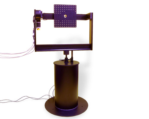
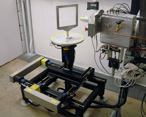
Petrographic Analysis Positioning Systems – Used for measuring air entrainment in concrete. Can be a UniSlide or BiSlide® System. For more details on Velmex systems for Petrographic Analysis, please visit the Velmex Petrographic System page. |
BiSlide Configurations
The basic BiSlide is a 1-axis linear stage. It can be configured a number of different ways and with multiple axes using the BiSlide T-Slot and framing system.
 |
||
 |
BiSlide® Specifications
Factors such as size of the motor, size of the payload, travel distance, mounting direction/plane, etc. effect the actual capability of any assembly. Please contact Velmex Application Engineers to configure a system that will meet your exact requirements.
| Motorized BiSlide® | Travel Distance‡ | Base Length (without motor) |
Slider Length | ||||
| Series* | Inches | cm | Inches | cm | Inches | cm | |
| MN10 – Precision Lead Screw | |
5" - 80" | 12.7 – 203.2 | 12.95" – 90.35" | 32.9 – 229.5 | 5" | 12.7 |
| MT10 – Tandem | |
5" - 80" | 12.7 – 203.2 | 12.95" – 90.35" | 32.9 – 229.5 | 5" | 12.7 |
| MR10 – Rapid Advance** | |
5" - 80" | 12.7 – 203.2 | 12.95" – 90.35" | 32.9 – 229.5 | 5" | 12.7 |
| MB10 – Belt Drive | |
10"†† - 228" | 25.4 – 579.12 | 27.3" – 245.3" | 68.34 – 623.1 | 8" | 20.32* |
| PC2 – Parallel-Coupled | |
up to 80" | up to 203.2 | Other specifications will depend on design of the specific system. See the Parallel-Coupled BiSlide page for more details. Talk to a Velmex Application Engineer. | |||
| PC2B – Parallel-Coupled, Belt-Drive | 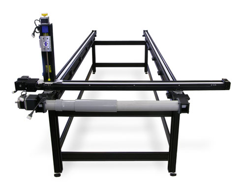 |
up to 220" | up to 559 | Other specifications will depend on design of the specific system. See the Parallel-Coupled BiSlide page for more details. Talk to a Velmex Application Engineer. | |||
* Motors sold separately. NEMA 23 units sold with .250" motor mounting coupling. NEMA 34 units sold with .375" motor mounting coupling.
**The Rapid Advance BiSlide Assembly is not recommended for vertical travel. Also only available in a "M01" 1 mm lead screw.
††While we offer 10" and 20" Belt-driven BiSlides for special applications, they are not recommended for practical use for high speed or continuous duty applications.
‡Standard travel distances available are in 5" increments up to 20" in length and 10" increments over 20".
For specifications on Parallel-Coupled BiSlides (PC2) see the Parallel-Coupled BiSlide page. For more detailed specifications, please call a Velmex Sales Application Engineer.
| Motorized BiSlide® | Weight† | Height | Width | ||||
| Series* | lbs. | kg. | Inches | cm | Inches | cm | |
| MN10 – Precision Lead Screw | |
6.9 – 33.6 | 3.2 – 15.3 | 3.03" | 7.7 | 3.4" | 8.64 |
| MR10 – Rapid Advance** | |
2.44" | 6.2 | 5.1" | 12.95 | ||
| MT10 – Tandem | |
12 – 60 | 5.4 – 27 | 3.03" | 7.7 | 6.8" | 17.27 |
| MB10 – Belt Drive | |
12.9 – 83.1 | 5.9 – 37.7 | 4.12" | 10.48 | 7.24" |
18.4 |
| Parallel-Coupled | |
Other specifications will depend on design of the specific system. See the Parallel-Coupled BiSlide page for more details. Talk to a Velmex Application Engineer. | |||||
† Weight of device without motor
* Motors sold separately. NEMA 23 units sold with .250" motor mounting coupling. NEMA 34 units sold with .375" motor mounting coupling.
**The Rapid Advance BiSlide Assembly is not recommended for vertical travel. Also only available in a "M01" 1 mm lead screw.
††While we offer 10" and 20" Belt-driven BiSlides for special applications, they are not recommended for practical use for high speed or continuous duty applications.
For specifications on Parallel-Coupled BiSlides (PC2) see the Parallel-Coupled BiSlide page. For more detailed specifications, please call a Velmex Sales Application Engineer.
| Motorized BiSlide® | Dynamic Load | Static Load | Momentary Load | |||
| Load Capacity | lbs. | kg. | lbs. | kg. | lbs. | kg. |
| MN10 | ||||||
| Maximum Centered | 300 lbs. | 136.1 | 300 lbs. | 136.1 | 1000 lbs. | 453.59 |
| Thrust | 100 lbs. | 45.36 | 200 lbs. | 90.72 | 300 lbs. | 136.1 |
| Cantilevered | 500 lbs.-in. | 56.5 n-m | ||||
| MT10 - Tandem | ||||||
| Maximum Centered | 600 lbs. | 272.15 | 600 lbs. | 272.15 | 2000 lbs. | 907.2 |
| Thrust | 100 lbs. | 45.36 | 200 lbs. | 90.72 | 300 lbs. | 136.1 |
| Cantilevered | 1000 lbs.-in. | 113.00 n-m | ||||
| MB10 - Belt Drive | ||||||
| Maximum Centered | 100 lbs. | 45.36 | 200 lbs. | 90.72 | 2000 lbs. | 907.2 |
| Thrust | 50 lbs. | 22.7 | 50 lbs. | 22.7 | 100 lbs. | 45.36 |
| Cantilevered | 500 lbs.-in. | 56.5 n-m | 500 lbs.-in. | 56.5 n-m | 500 lbs.-in. | 56.5 n-m |
| MR10 – Rapid Advance** | ||||||
|---|---|---|---|---|---|---|
| Maximum Centered | 150 lbs. | 68.04 | 150 lbs. | 68.04 | ||
| Thrust | 3 lbs. | 1.4 | 15 lbs. | 6.8 | ||
**The Rapid Advance BiSlide Assembly is not recommended for vertical travel. Also only available in a "M01" 1 mm lead screw.
| Coefficient of friction | 0.09 typical |
| Coefficient range | 0.04 (Heavy Load Dynamic) to 0.15-0.3 (Lubricated Heavy Load Static) >1 hour) |
| Minimum motor torque required | 55 oz-in (0.4 N-M) |
| Repeatability | 0.0002" over short term, long term dependent on wear |
| Straight line accuracy | 0.003" (0.076 mm) over entire travel distance. Higher accuracy 0.0015" (0.038mm) available |
| Screw lead accuracy | 0.003"/10" (0.076 mm/25 cm) 0.0015"/10" available. Consult factory. |
| Operating temperature | 0 to 180° F (-18 to 82° C) |
| Properties of Velmex Stages | Information on stage composition, tolerances, wear and design for specialty applications. |
| Load Parameters | Definitions and parameters that effect the various load ratings. |
Lead Screws
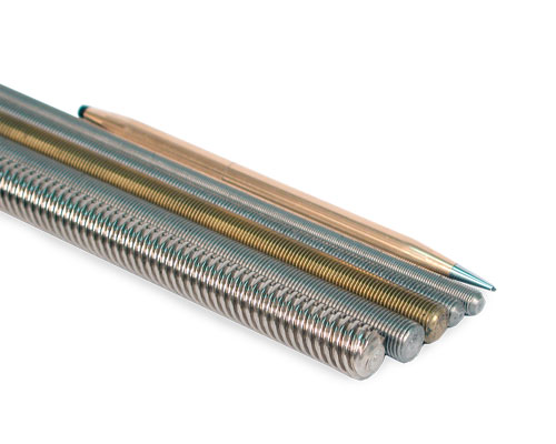 A wide selection of high-quality lead screws provide flexibility in designing the drive portion of Velmex translation stages.
The lead screws we use are all manufactured by us to exacting standards. They are formed by rolling through precision dies rather than cutting on a screw machine, resulting in higher quality and accuracy. The screws are made of either 303 stainless steel or electroless nickel-plated, cold rolled steel. Other materials are available for specialized applications. Please check with our Application Engineers for details.
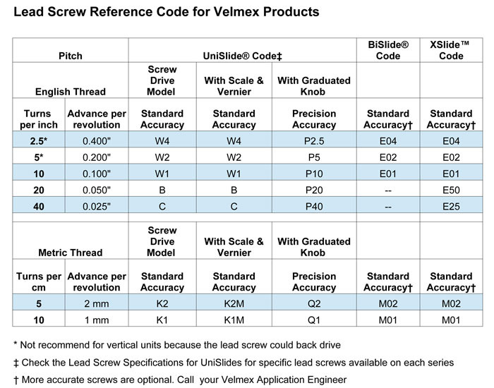
The lead screws are available in a range of diameters with both English and Metric Threads. The pitch for English Thread lead screws range from 2.5 turns per inch to 40 turns per inch. The Metric lead screws range from 5 turns to 10 turns per metric thread. We offer both Standard accuracy and Precision accuracy (Precision grade) screws.
The following chart shows the lead screw specifications for motorized BSlide Stages, along with our other Velmex products.
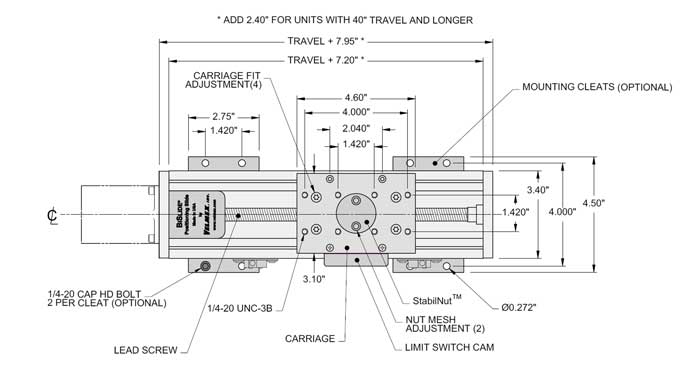
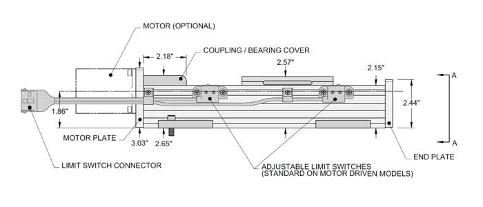
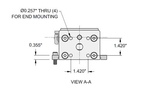
BiSlide® Dimensions (Shown with optional motors and cleats) |
|||
|---|---|---|---|
| ‡Standard travel distances available are in 5" increments up to 20" in length and 10" increments over 20". | |||
| View from Top | |||
 |
|||
| View from Side | |||
 |
|||
| View from End | Carriage | ||
 |
 |
||
To function efficiently single axis BiSlide Assemblies should be mounted to a flat surface. Cleating Recommendations.
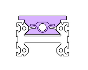
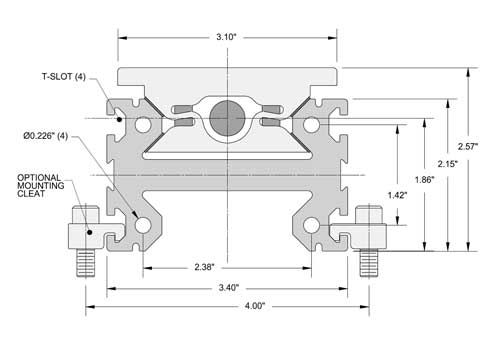
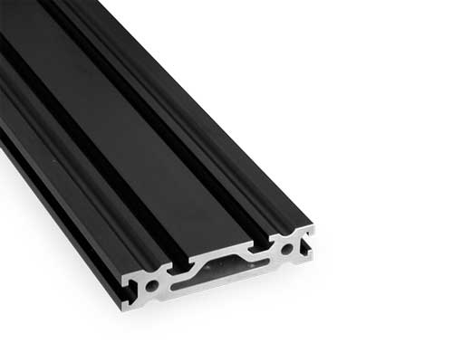
BiSlide Base Cross-Section
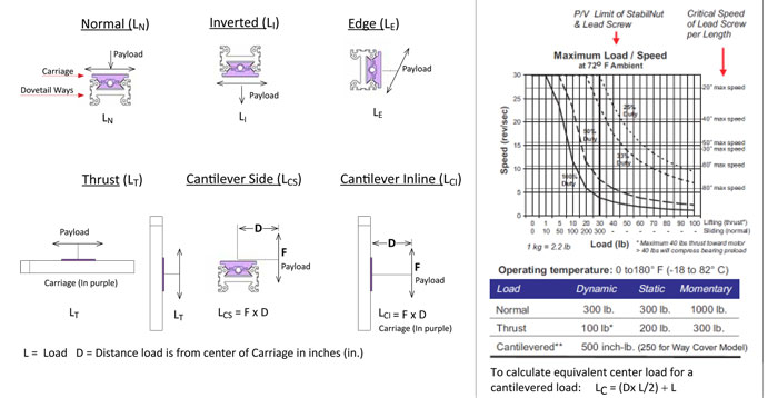
The slider / carriage (shaded area in the cross-section to the left) rides inside the guide ways. The 45 degree opposing ways give strength to carry the payload.
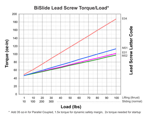
BiSlide Load Calculations
 |
|
| Enlarge Chart | |
| 1Note: Because of the interlocking nature of the BiSlide carriage and the dovetail ways, the maximum recommended load centered (normal) or under thrust would be comparable whether the slide was upright (Normal – LN), Inverted (LI) or set on the Edge (LE). |
|
|

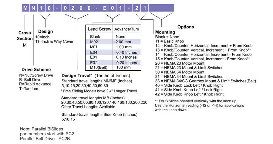
BiSlide Part Number Configuration
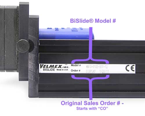
All BiSlide Assemblies have the same basic part number configuration. (Check this page for a part number schematic for the Belt Drive BiSlide.) The number varies with the series, the travel distance, the lead screw and the slider length. Additional prefixes and suffixes are added for the options and accessories. You can determine the BiSlide part number using the chart below. The number can be found on the side or end of any Velmex device you may already own.
 |
The part number can be found on the side of the BiSlide Assembly. |
 |
|---|
![]() BiSlide Assemblies conform to European Machinery Directive (89/392/EEC) Annex 1
BiSlide Assemblies conform to European Machinery Directive (89/392/EEC) Annex 1
Options/Accessories for Motorized Velmex BiSlides®
The Velmex BiSlide framing options and various accessories allow the user to create complete multi-axis, high accuracy positioning systems quickly and easily.
BiSlide Framing - The versatility of the BiSlide's modular design enables building of complex configurations. A variety of framing components can be combined and connected, disassembled and reassembled in alternate configurations to build BiSlide structures as needed. For more specifics and to see the framing components, including plates and brackets, in use on a BiSlide stage visit the BiSlide Adapters page. |
||
 |
T-Slot Plate – rugged, hard anodized aluminum extrusions with abundant T-slots for multiple attachment possibilities. The T-Slot Plate creates a heavy-duty support structure for building BiSlide mounting and framing structures or configuring multiple coordinates. |
|
 |
I-Beam BiSlide Base –The extruded I-beam base is made from a hard alloy aluminum and includes T-slots on each side to easily connect BiSlides to each other or attach the BiSlide to a frame or base structure. |
|
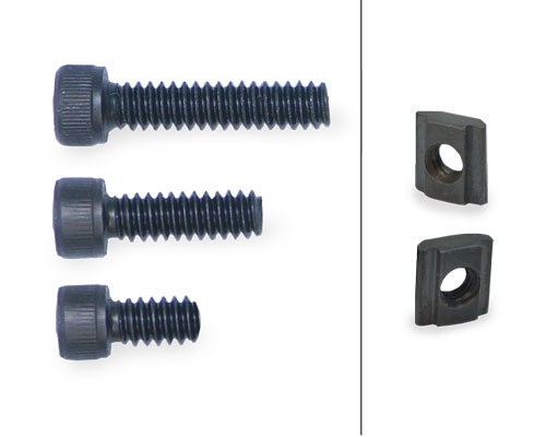 |
T-Nuts , mounting bolts and other hardware – to create strong, secure attachments. Can also be used with the cleats. |
|
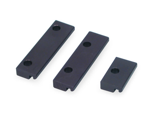 |
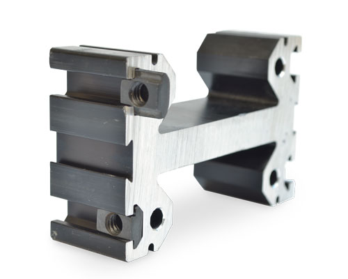
Cleats - use BiSlide cleats to create rigid XY attachments, mountings for optical tables and attachments to other T-slot framing systems. The cleats are also used to secure BiSlides for longer travel distances and to support larger loads. Cleating Recommendations. |
|
MC-1 – Standard 1 hole cleat. Mounts the BiSlide to a frame / base / surface. Can be used to mount to other BiSlides in an XY, XZ or XYZ configuration. |
||
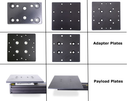 |
Adapter Plates and Spacers – use BiSlide adapter plates for vertical mounts; to create a larger base support; to mount Velmex rotary tables and turntables to the BiSlide; to as auxiliary payload mounting plates to support larger payload footprints. For more specifics and to see the framing components, including plates and brackets, in use on a Velmex stage visit the BiSlide Adapters page. |
|
MSPP-1 Foot Plate – Used as part of the foot for BiSlide bases and post assemblies. |
||
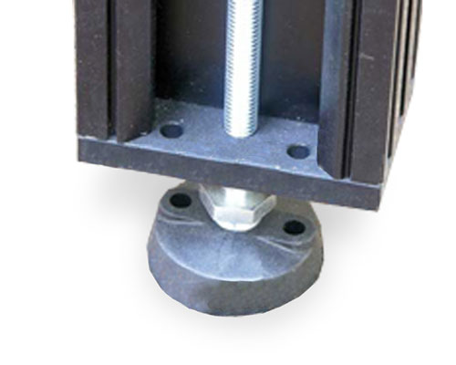 |
Foot – Acts as an adjustable foot for BiSlide bases and post assemblies. (LFS-1) (Shown with a MSPP-1 foot plate.) |
|
 |
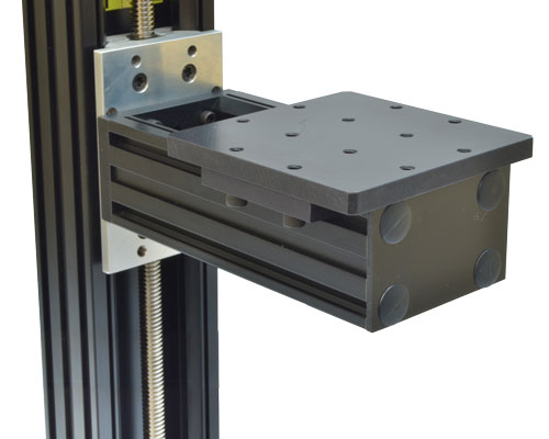
Angle Brackets and Gussets – Use XZ angle brackets and gussets as braces for vertical BiSlide assemblies perpendicular to the X or Y plane to provide higher rigidity. They are available in various sizes for vertical and gantry mounting. For more specifics and to see the framing components, including plates and brackets, in use on a Velmex stage visit the BiSlide Adapters page. |
|
 |
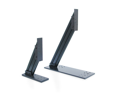
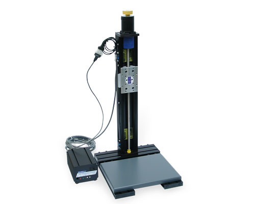
Post Assemblies –Attach at right angles to the BiSlide Assembly to provide a convenient method to connect rotary tables or other accessories at a right angle, a distance from the carriage surface. Supports an adapter plate either vertically or horizontally. |
|
|
Preconfigured Frames/Bases – See BiSlide Adapters for more information. |
|
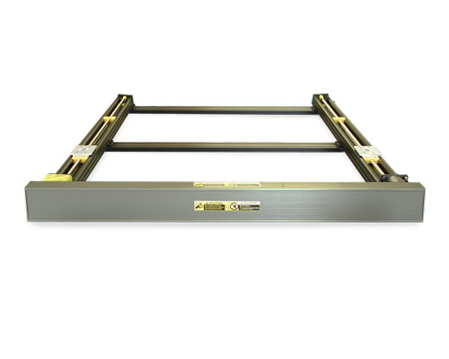
F2 Style has I-Beam top rails running parallel on two sides. These are ideal for supporting parallel coupled BiSlide Assemblies. |
||
 |
Additional Carriages - Additional carriages (sliders) can be added to all models of BiSlides to increase the carrying capacity of the slide. |
|
|
Left-Right screw motion - This configuration is very useful for applications where two objects must share a common axis of movement. This assembly incorporates two carriages driven by a single right- and left-hand threaded lead screw. When the knob is turned, the carriages simultaneously move toward or away from each other.
|
|
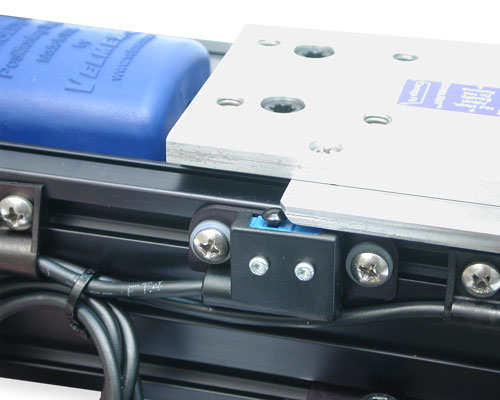 |
Outboard Adjustable Limit Switches– Mounted in a track on the side rib of Velmex BiSlide Assemblies to prevent over-travel. An optional third limit switch can be added between the two standard limits and used as an adjustable home switch. See Limits for more information. |
|
|
||
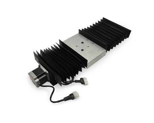 |
Way Covers (-WC) – Protect the slider and dovetail base from dust, dirt and grit that could hamper the efficient operation of the slide. They also extend the slide's life. Way covers increase slider height and reduce the travel length of linear BiSlide stages. |
|
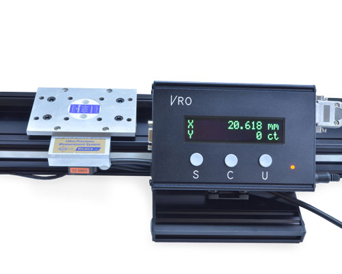 |
Encoders and VRO™ Encoder Readout – For a high resolution position readout an encoder and Velmex's VRO encoder readout can be mounted to most linear BiSlide assemblies. An encoder, mounted directly to the slider gives a true and accurate reading eliminating lead screw and backlash errors. The VRO is compatible with all 5V incremental encoders. It can monitor one or two axis. Fully functional, it features automatic memory back-up of settings, sleep mode and self diagnostics. It's highly visible, wide-screen LED display makes it easy to view the positioning results. SEE: Velmex Controls on the Encoders and the VRO Readout for additional details. |
|
 |
Motorized / Manual Operation - All BiSlides are designed to accommodate NEMA size 23 and size 34 motors without modifications. They are the easiest to convert from manual operation to motorized. Simply remove the knob and mount the motor. Then add limit switches.
(Conversion kit pcitured - Motor sold separately.) |
|
 |
Motorized / Manual Operation– It is possible, using a double shaft motor, to produce a Velmex stage that can be manually operated or motor-driven. A shaft extension accommodates the either a Rogan or standard aluminum knob. |
|
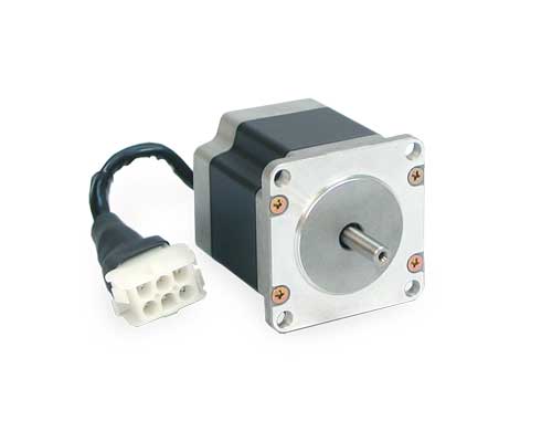 |
Motors - BiSlides are compatible with Nema DC step motors – 23 or 34. Other motors including gear motors, servo motors and high resolution step motors in both AC and DC can run Velmex BiSlides. Motor-driven BiSlide Assemblies are motor-ready. The motor is purchased separately. Customers can mount their own motors, if they chose. SEE: Velmex Controls on the Motors for additional details. |
|
 |
VXM™ Controller - Step motors coupled with a motor controller like the Velmex VXM™ are a cost effective solution for accurate speed and precise incremental positioning. Gear motors, servo motors and high resolution step motors in both AC and DC can run Velmex UniSlides. SEE: Velmex Controls on the VXM Controller for additional details. |
|
Velmex offers a multitude of options and accessories for all its products. Usually an option or an accessory will address your requirements. When it doesn't we can make custom modifications, including:
• Additional holes or slots. (A drawing is required.)
• Intermediate plates to mount your payload
• Special or in between lengths of the dovetail base
• Lead screw shaft extensions
• Choice of drive nut materials, including brass and Vespel
• Right and left-hand threads on the same lead screw, allowing a pair of sliders to move together or apart
We can also offer customized configurations to address special environmental and vacuum applications.
Motorized BiSlide CAD Drawings / Documents / Instructions
The majority of CAD drawings found in our Technical Library are Step (.stp) files. You will also see .dxf, .dwg, .sat and .pdf files. For .STP files, you may need to right click on the download button and save the "target" or "link". If you require a different format or cannot located the drawing you require, please contact us. Drawings are identified by the series or configuration. The complete part number can be found on the side or end of any Velmex device you may already own.
NOTE: Lead Screw pitch variations are represented by a single drawing number. For example - MN10-0100-E04-21 becomes MN10-0100-XXX-21
For non-standard sizes or multi-axis configurations, please contact us. There may be an additional charge.
| Click to open the section you need: | "Right Click" to download. |
| Series | Type | File Name | Description | Download | View |
|---|---|---|---|---|---|
| 5" travel | |||||
| MN10 | STP | MN10-0050-xxx-21 2Cleats PK266.stp | Lead screw, 5" Travel, PK266 stepper - 2 Cleats | - | |
| MN10 | STP | MN10-0050-xxx-21 4Cleats PK266.stp | Lead screw, 5" Travel, PK266 stepper - 4 Cleats | - | |
| MN10 | STP | MN10-0050-xxx-21 PK266.stp | Lead screw, 5" Travel, PK266 stepper | - | |
| MN10 | SAT | MN10-0050-xxx-31.sat | Lead screw, 5" Travel, Nema 34 stepper | - | |
| 10" travel | |||||
| MN10 | STP | MN10-0100-xxx-21 2Cleats PK266.stp | Lead screw,10" Travel, PK266 stepper - 2 Cleats | - | |
| MN10 | STP | MN10-0100-xxx-21 4Cleats PK266.stp | Lead screw,10" Travel, PK266 stepper - 4 Cleats | - | |
| MN10 | STP | MN10-0100-xxx-21 6Cleats PK266.stp | Lead screw,10" Travel, PK266 stepper - 6 Cleats | - | |
| MN10 | STP | MN10-0100-xxx-21 PK266.stp | Lead screw,10" Travel, PK266 stepper | - | |
| MN10 | SAT | MN10-0100-xxx-31.sat | Lead screw, 10 " Travel, Nema 34 stepper | - | |
| 15" travel | |||||
| MN10 | STP | MN10-0150-xxx-21 2Cleats PK266.stp | Lead screw,15" Travel, PK266 stepper - 2 Cleats | - | |
| MN10 | STP | MN10-0150-xxx-21 4Cleats PK266.stp | Lead screw,15" Travel, PK266 stepper - 4 Cleats | - | |
| MN10 | STP | MN10-0150-xxx-21 8Cleats PK266.stp | Lead screw,15" Travel, PK266 stepper - 8 Cleats | - | |
| MN10 | STP | MN10-0150-xxx-21 PK266.stp | Lead screw,15" Travel, PK266 stepper | - | |
| MN10 | SAT | MN10-0150-xxx-31.sat | Lead screw, 15" Travel, Nema 34 stepper | - | |
| 20" travel | |||||
| MN10 | STP | MN10-0200-xxx-21 2Cleats PK266.stp | Lead screw, 20" Travel, PK266 stepper - 2 Cleats | - | |
| MN10 | STP | MN10-0200-xxx-21 6Cleats PK266.stp | Lead screw, 20" Travel, PK266 stepper - 6 Cleats | - | |
| MN10 | STP | MN10-0200-xxx-21 10Cleats PK266.stp | Lead screw, 20" Travel, PK266 stepper - 10 Cleats | - | |
| MN10 | STP | MN10-0200-xxx-21 PK266.stp | Lead screw, 20" Travel, PK266 stepper | - | |
| MN10 | SAT | MN10-0200-xxx-31.sat | Lead screw, 20 " Travel, Nema 34 stepper | - | |
| 30" travel | |||||
| MN10 | STP | MN10-0300-xxx-21 2Cleats PK266.stp | Lead screw, 30" Travel, PK266 stepper - 2 Cleats | - | |
| MN10 | STP | MN10-0300-xxx-21 8Cleats PK266.stp | Lead screw, 30" Travel, PK266 stepper - 8 Cleats | - | |
| MN10 | STP | MN10-0300-xxx-21 12Cleats PK266.stp | Lead screw, 30" Travel, PK266 stepper - 12 Cleats | - | |
| MN10 | STP | MN10-0300-xxx-21 PK266.stp | Lead screw, 30" Travel, PK266 stepper | - | |
| MN10 | SAT | MN10-0300-xxx-31.sat | Lead screw, 30 " Travel, Nema 34 stepper | - | |
| 40" travel | |||||
| MN10 | STP | MN10-0400-xxx-31 10Cleats PK296.stp | Lead screw, 40" Travel, PK296 stepper - 10 Cleats | - | |
| MN10 | STP | MN10-0400-xxx-31 14Cleats PK296.stp | Lead screw, 40" Travel, PK296 stepper - 14 Cleats | - | |
| MN10 | STP | MN10-0400-xxx-31 PK296.stp | Lead screw, 40" Travel, PK296 stepper | - | |
| 50" travel | |||||
| MN10 | STP | MN10-0500-xxx-31 12Cleats PK296.stp | Lead screw, 50" Travel, PK296 stepper - 12 Cleats | - | |
| MN10 | STP | MN10-0500-xxx-31 16Cleats PK296.stp | Lead screw, 50" Travel, PK296 stepper - 16 Cleats | - | |
| MN10 | STP | MN10-0500-xxx-31 PK296.stp | Lead screw, 50" Travel, PK296 stepper | - | |
| 60" travel | |||||
| MN10 | STP | MN10-0600-xxx-31 14Cleats PK296.stp | Lead screw, 60" Travel, PK296 stepper - 14 Cleats | - | |
| MN10 | STP | MN10-0600-xxx-31 18Cleats PK296.stp | Lead screw, 60" Travel, PK296 stepper - 18 Cleats | - | |
| MN10 | STP | MN10-0600-xxx-31 PK296.stp | Lead screw, 60" Travel, PK296 stepper | - | |
| 80" travel | |||||
| MN10 | STP | MN10-0800-xxx-31 16Cleats PK296.stp | Lead screw, 80" Travel, PK296 stepper - 16 Cleats | - | |
| MN10 | STP | MN10-0800-xxx-31 20Cleats PK296.stp | Lead screw, 80" Travel, PK296 stepper - 20 Cleats | - | |
| MN10 | STP | MN10-0800-xxx-31 PK296.stp | Lead screw, 80" Travel, PK296 stepper | - | |
| Series | Type | File Name | Description | Download | View |
|---|---|---|---|---|---|
| MT10 | STP | MT10-0050-xxx-31 4Cleats PK296.stp | Tandem, Lead screw, BiSlide, 5" Travel, PK296 Stepper- 4 Cleats | - | |
| MT10 | STP | MT10-0100-xxx-31 6Cleats PK296.stp | Tandem, Lead screw, BiSlide, 10" Travel, PK296 Stepper- 6 Cleats | - | |
| MT10 | STP | MT10-0150-xxx-31 8Cleats PK296.stp | Tandem, Lead screw, BiSlide, 15" Travel, PK296 Stepper- 8 Cleats | - | |
| MT10 | STP | MT10-0200-xxx-31 10Cleats PK296.stp | Tandem, Lead screw, BiSlide, 20" Travel, PK296 Stepper- 10 Cleats | - | |
| MT10 | STP | MT10-0300-xxx-31 12Cleats PK296.stp | Tandem, Lead screw, BiSlide, 30" Travel, PK296 Stepper- 12 Cleats | - | |
| MT10 | STP | MT10-0400-xxx-31 14Cleats PK296.stp | Tandem, Lead screw, BiSlide, 40" Travel, PK296 Stepper- 14 Cleats | - | |
| MT10 | STP | MT10-0500-xxx-31 16Cleats PK296.stp | Tandem, Lead screw, BiSlide, 50" Travel, PK296 Stepper- 16 Cleats | - | |
| MT10 | STP | MT10-0600-xxx-31 18Cleats PK296.stp | Tandem, Lead screw, BiSlide, 60" Travel, PK296 Stepper- 18 Cleats | - | |
| MT10 | STP | MT10-0800-xxx-31 20Cleats PK296.stp | Tandem, Lead screw, BiSlide, 80" Travel, PK296 Stepper- 20 Cleats | - |
| Series | Type | File Name | Description | Download | View |
|---|---|---|---|---|---|
| 10" Travel | |||||
| MB10 | SAT | MB10_0100_M100_33_6Cleats_PK296xx-SGxx.sat | Belt Drive, 10" Travel, PK296 Stepper - 6 Cleats | - | |
| MB10 | STP | MB10_0100_M100_33_6Cleats_PK296xx-SGxx.stp | Belt Drive, 10" Travel, PK296 Stepper - 6 Cleats | - | |
| 20" Travel | |||||
| MB10 | SAT | MB10_0200_M100_33_6Cleats_20in Beltdrive.sat | Belt Drive, 20" Travel - 6 Cleats | - | |
| MB10 | STP | MB10_0200_M100_33_6Cleats_PK296_20in Beltdrive.stp | Belt Drive, 20" Travel, PK296 Stepper - 6 Cleats | - | |
| 30" Travel | |||||
| MB10 | SAT | MB10_0300_M100_33_8Cleats_30in Beltdrive.sat | Belt Drive, 30" Travel - 8 Cleats | - | |
| MB10 | STP | MB10_0300_M100_33_8Cleats_PK296_30in Beltdrive.stp | Belt Drive, 30" Travel, PK296 Stepper - 8 Cleats | - | |
| 40" Travel | |||||
| MB10 | SAT | MB10_0400_M100_33_10Cleats_40in Beltdrive.sat | Belt Drive, 40" Travel - 10 Cleats | - | |
| MB10 | STP | MB10_0400_M100_33_10Cleats_PK296_40in Beltdrive.stp | Belt Drive, 40" Travel, PK296 Stepper - 10 Cleats | - | |
| 50" Travel | |||||
| MB10 | SAT | MB10_0500_M100_33_12Cleats_50in Beltdrive.sat | Belt Drive, 50" Travel - 12 Cleats | - | |
| MB10 | STP | MB10_0500_M100_33_12Cleats_PK296xx-SGxx_50in Beltdrive.stp | Belt Drive, 50" Travel, PK296 Stepper - 12 Cleats | - | |
| 60" Travel | |||||
| MB10 | SAT | MB10_0600_M100_33_14Cleats_50in Beltdrive.sat | Belt Drive, 60" Travel - 14 Cleats | - | |
| MB10 | STP | MB10_0600_M100_33_14Cleats_PK296xx-SGxx_60in Beltdrive.stp | Belt Drive, 60" Travel, PK296 Stepper - 14 Cleats | - | |
| 80" Travel | |||||
| MB10 | SAT | MB10_0800_M100_33_16Cleats_80in Beltdrive.sat | Belt Drive, 80" Travel - 16 Cleats | - | |
| MB10 | STP | MB10_0800_M100_33_16Cleats_PK296xx-SGxx_.stp | Belt Drive, 80" Travel, PK296 Stepper - 16 Cleats | - | |
| 100" Travel | |||||
| MB10 | SAT | MB10_1000_M100_33_18Cleats_100in Beltdrive.sat | Belt Drive, 100" Travel - 18 Cleats | - | |
| MB10 | STP | MB10_1000_M100_33_18Cleats_PK296xx-SGxx_100in Beltdrive.stp | Belt Drive, 100" Travel, PK296 Stepper - 18 Cleats | - | |
| 120" Travel | |||||
| MB10 | SAT | MB10_1200_M100_33_20Cleats_120in Beltdrive.sat | Belt Drive, 120" Travel - 20 Cleats | - | |
| MB10 | STP | MB10_1200_M100_33_20Cleats_PK296xx-SGxx_120in Beltdrive.stp | Belt Drive, 120" Travel, PK296 Stepper - 20 Cleats | - | |
| 140" Travel | |||||
| MB10 | SAT | MB10_1400_M100_33_22Cleats_140in Beltdrive.sat | Belt Drive, 140" Travel - 22 Cleats | - | |
| MB10 | STP | MB10_1400_M100_33_22Cleats_PK296xx-SGxx_140in Beltdrive.stp | Belt Drive, 140" Travel, PK296 Stepper - 22 Cleats | - | |
| 160" Travel | |||||
| MB10 | SAT | MB10_1600_M100_33_24Cleats_160in Beltdrive.sat | Belt Drive, 160" Travel - 24 Cleats | - | |
| MB10 | STP | MB10_1600_M100_33_24Cleats_PK296xx-SGxx_160in Beltdrive.stp | Belt Drive, 160" Travel, PK296 Stepper - 24 Cleats | - | |
| 180" Travel | |||||
| MB10 | SAT | MB10_1800_M100_33_26Cleats_180in Beltdrive.sat | Belt Drive, 180" Travel - 26 Cleats | - | |
| MB10 | STP | MB10_1800_M100_33_26Cleats_PK296xx-SGxx_180in Beltdrive.stp | Belt Drive, 180" Travel, PK296 Stepper - 26 Cleats | - | |
| 200" Travel | |||||
| MB10 | SAT | MB10_2000_M100_33_28Cleats_200in Beltdrive.sat | Belt Drive, 200" Travel - 28 Cleats | - | |
| MB10 | STP | MB10_2000_M100_33_28Cleats_PK296xx-SGxx_200in Beltdrive.stp | Belt Drive, 200" Travel, PK296 Stepper - 28 Cleats | - | |
| 220" Travel | |||||
| MB10 | SAT | MB10_2200_M100_33_30Cleats_220in Beltdrive.sat | Belt Drive, 220" Travel - 30 Cleats | - | |
| MB10 | STP | MB10_2200_M100_33_30Cleats_PK296xx-SGxx_220in Beltdrive.stp | Belt Drive, 220" Travel, PK296 Stepper -30 Cleats | - | |
| Series | Type | File Name | Description | Download | View |
|---|---|---|---|---|---|
| PC2 | SAT | BiSlide Parallel Coupled XX 33in ctr to ctr 25in travel 2 supports.sat | Motorized, Parallel-Coupled BiSlide with 25" Travel, set 33" center to center, with 2 supports to the frame | - | |
| PC2 | STP | BiSlide Parallel Coupled XX 33in ctr to ctr 25in travel 2 supports.stp | Motorized, Parallel-Coupled BiSlide with 25" Travel, set 33" center to center, with 2 supports to the frame | - | |
| PC2 | SAT | BiSlide Parallel Coupled XX 33in ctr to ctr 30in travel 2 supports.sat | Motorized, Parallel-Coupled BiSlide with 30" Travel, set 33" center to center, with 2 supports to the frame | - | |
| PC2 | STP | BiSlide Parallel Coupled XX 33in ctr to ctr 30in travel 2 supports.stp | Motorized, Parallel-Coupled BiSlide with 30" Travel, set 33" center to center, with 2 supports to the frame | - | |
| PC2B | SAT | BiSlide Beltdrive Parallel 120in ctr to ctr.sat | Motorized, Parallel-Coupled, Belt-Driven BiSlide with ±100" Travel, set 120" center to center, with 2 supports to the frame | - | |
| PC2B | STP | BiSlide Beltdrive Parallel 120in ctr to ctr.stp | Motorized, Parallel-Coupled, Belt-Driven BiSlide with ±100" Travel, set 120" center to center, with 2 supports to the frame | - |
| Type | File Name | Description | Download | View |
|---|---|---|---|---|
| STP / PDF | BiSlide Cleat MC-1 | BiSlide - MC-1 Cleat | ||
| STP / PDF | BiSlide Cleat MC-2 | BiSlide - MC-2 Cleat | ||
| STP / PDF | BiSlide Optical Table Cleat MC-3 | BiSlide - MC-3 Cleat for Optical Table Mounting | ||
| STP | GST-1-FX.stp | XZ Bracket (10" x13") Free Standing | - | |
| STP | GST-1-L.stp | XZ Bracket in line | - | |
| STP | GST-2-FX.stp | XZ Bracket Free Standing | - | |
| STP | GST-2-L.stp | XZ Bracket in line | - | |
| STP | IM001-61 MSPP-1 Adjustable foot plate.stp | Adjustable foot for BiSlide bases and post assemblies. | - | |
| STP | IM001-104 MSPP-2 Standard Universal Plate.stp | Multi-purpose adapter plate (4.6" c 4.6" X 0.375") | ||
| STP / PDF | IM001-105 MSPP-3 4800 BiSlide plate | Adapter plate to mount Rotary Table (A48 or B48 Series) to BiSlide | ||
| STP | IM001-106 MSPP-4 5990 Plate.stp | Adapter plate to mount Rotary Table (A59 or B59 Series) to BiSlide | - | |
| STP | IM001-107 MSPP-5 End Mounted Plate.stp | Adapter plate to end mount BiSlide extrusion. | - | |
| STP | IM001-108 MSPP-6 Optical Plate.stp | Adapter plate to end mount BiSlideto an optical bench | - | |
| STP / PDF | IM001-130-131 8x8 Top Plate with Standoffs | BiSlide payload plate to expand the carriage (8" x 8" x 0.375") | ||
| IM001-132 12x12 Top Plate.pdf | BiSlide payload plate to expand the carriage (12" x 12" x 0.375") | |||
| STP / PDF | MSPP-10A Two carriages in one slide body with mounting holes | Tandem BiSlide Plate to connect to dual carriages together. | ||
| IM003-1-T-nut.vcd | T-nut | - |
BiSlide Documents
| Type | File Name | Description | Download | View |
|---|---|---|---|---|
| BiSlide Dimensional Drawing.pdf | 2D Dimensional Drawings | |||
| BiSlide Spec Overview.pdf | Specfications and features for BiSlide Assembly | |||
| BiSlide Users Manual 2021.pdf | User's Operating Manual for BiSlide Assemblies built after March 2019 with StabiNut II™ drive nut. | |||
| BiSlide Users Manual.pdf | User's Operating Manual for BiSlide Assemblies built before March 2019 with StabliNut I™ drive nut. | |||
| BiSlide Belt Drive Info Sheet.pdf | Specfications and features for the Belt Drive BiSlide Assembly | |||
| BiSlide Side Knob Info Sheet.pdf | Specifications and features for BiSlide Side Knob Assembly |
BiSlide Instructions
| Type | File Name | Description | Download | View |
|---|---|---|---|---|
| BiSlide - Attaching Elgo Magnetic Encoder - 714.pdf | Instructions - Attaching Magnetic Encoder | |||
| Bislide base F2 assy.pdf | Instructions - Assembly of F2 base | |||
| Bislide base F4 assy rev2.pdf | Instructions - Assembly of F4 base | |||
| BiSlide Belt Drive Parallel Coupled Assy.pdf | Instructions - Assembly of the Parallel-Coupled Belt-Drive (motor-driven) BiSlide System | |||
| BiSlide PC4 Parallel Coupled .pdf | Instructions - Assembly of the Parallel-Coupled BiSlide System - PC4 | |||
| Parallel Coupled Assembly Instructions.pdf | Instructions - Assembly of the Parallel-Coupled Lead Screw (motor-driven) BiSlide System - external motor - PC2 | |||
| BiSlide Cleat Recommendations.pdf | Instructions - Number and position of cleats recommended for BiSlide Assemblies | |||
| BiSlide Bearing Assembly Procedure.pdf | Instructions - Procedure to assemble the bearing and re-establish the preload in the field. | |||
| BiSlide Way Cover Install BWC-P1.pdf | Instruction - Installing Way Covers on the linear BiSlide |
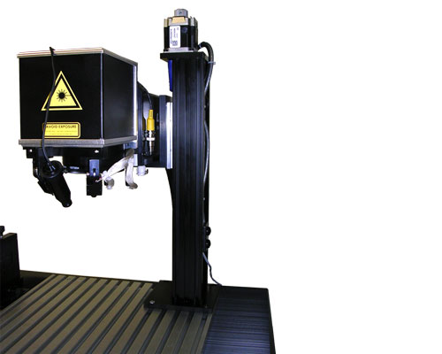
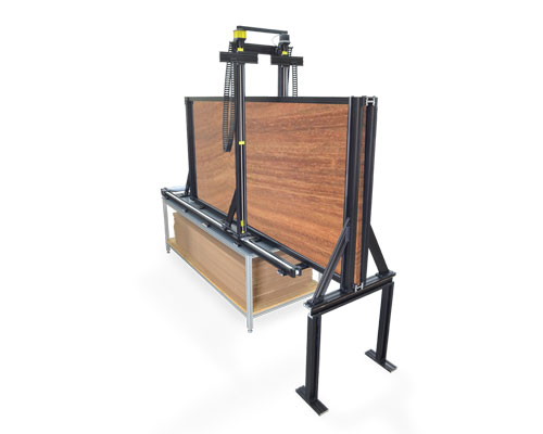
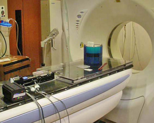
Velmex BiSlide® Applications and Examples
These are examples of Velmex products. If you wish a similar product, please contact us with your specific application specifications (travel distance, payload, hours per day in use, resolution, speed range, etc.). You can use the Request Assistance form. |
Pictured in our gallery are examples of configurations for both manual and motorized BiSlides, along with configurations that also include other Velmex products. Product and accessory offering is subject to change and availability.
| Example Key Code | Meaning | Example Key Code | Meaning |
|---|---|---|---|
| A | Manually Operated | M | Motorized |
| S | Standard | C | Custom Configuration |
| B | BiSlide | U | UniSlide |
| X | XSlide | R | Rotary Tables |
| T | XY Tables | TT | Turntables |
| E | Elevating Tables | FS | Fun Stuff (Ingenious, Cool, or Just out of the ordinary applications) |
|
|
|
|
|
|
|
|
|
|
|
|
|
|

|
|
|
|
|
|
Velmex also offers manual BiSlide Assemblies. Examples of other Velmex products can be found on the Examples page or in the Examples section for each product.
Many questions can be answered by reviewing the "Features", "Model / Series", "Specifications", "Options / Accessories" and "Technical Documentation" sections for each product line. Additional FAQs about product comparisons, product construction, purchasing and shipping can be found on the company FAQ page.
BiSlide Stage Troubleshooting
First - always read the Users Manual.
| Symptom | Possible Cause | Possible Fixes |
|---|---|---|
| The carriage binds or will not move. | During mounting, the base may have been over-tightened or mounted to an irregular surface. This can distort the assembly, causing carriage binding. | Loosen screws and re-tighten to the proper torque. |
| Tighten bolts in cleats to 95 in-lbs. | ||
| Remount base to a flat surface. (Recommend: Mounting surface should be steel or aluminum and have 1/4-20 UNC threaded holes with a minimum thread depth of 0.30".) | ||
| Mounting non-flat plate or blocks to the carriage to hold the load can also distort the assembly, causing carriage binding. Anything attached to the assembly must be mounted flat to the carriage. | Use the "finger test" to check for binding. Grasp the lead screw on either side of the carriage and twist. If the lead screw can't be moved, the slide or the load may not be mounted properly or the mounting bolts are too tight. (CAUTION: Over tightening will increase friction, could stall the motor and cause increased wear.) | |
| There is some backlash in the carriage on a motorized BiiSlide. | Some backlash maybe seen when the lead screw and carriage start to wear. | Adjust by tightening the Allen cap screw on the top of the drive nut. (CAUTION: Over tightening will increase friction, could stall the motor and cause increased wear.) |
| Use the "finger test" to check for binding. Grasp the lead screw on either side of the carriage and twist. If the lead screw can't be moved, the slide or the load may not be mounted properly or the mounting bolts are too tight. | ||
| There appears to be free-play on a motorized BiSlide. This may be accompanied by a clunking/knocking noise when pulling up and down on the corners of the carriage. | Objectionable play can be reduced by tightening the four carriage fit bolts on the carriage surface. | Adjust each bolt equally a maximum of 1/8 of a turn. (CAUTION: Over tightening will increase friction, could stall the motor and cause increased wear.) |
| Carriage appears to be at a slight angle and out of parallel with the base. | ||
| The limit switches are failing. | An out of parallel carriage may angle the limit switch actuator cam to be either too high or low resulting in limit switch failure. | |
| The carriage seems to clunk when pulling and pushing on one diagonal of the carriage. | The Carriage Fit Bolts may not have been tightened equal. | Back off on slightly on the adjustment bolts on the opposite diagonal and re-tighten all 4 bolts equally to 1/8 maximum turn. Use a level and check for parallelism to the base. (See User's Manual.) |
Do BiSlides need lubrication and how often?
Lubrication is important for motor-driven systems or wherever you want maximum life and the lowest friction. BiSlide Assemblies should be lubricated with Velmex BL-1 oil. Only a few drops are required to keep your slide running smoothly. The load and hours of use effect the amount and frequency of lubrication. Manual BiSlide assemblies require less frequent lubrication. See the user guide that came with your BiSlide for recommendations.
Can BiSlides be mounted together?
Yes, BiSlides can be mounted together in XY, XZ, XYZ configurations. Mounting BiSlide assemblies in multi-axis systems is easy using cleats. T-slot bases and frames can be added for more structure and to create application specific systems. They also can be combined with Velmex Rotary Tables and our other linear stages to make custom systems for a wide range of requirements. See BiSlide Options and Accessories for more information on the cleats and T-slot structuring.
How do I mount a BiSlide to my working surface?
BiSlides typically are mounted to any surface with the BiSlide cleats. The surface should be flat to avoid binding, operate smoothly and accurately. Steel or aluminum are recommended for the surface. For heavy loads, you start with 2 pair of cleats (4) and add a pair for every 5" in travel. Lighter loads would require fewer cleats.
How do you adjust the carriage fit on an BSlide?
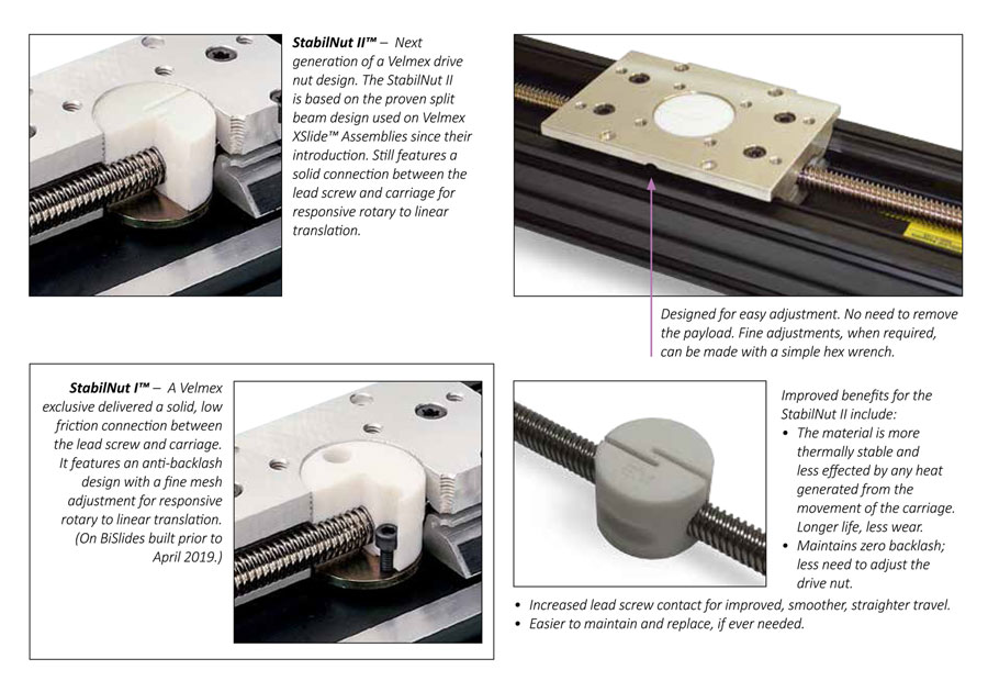
Adjustments the carriage on a BiSlide may be necessary after break in period and less frequently thereafter. The Lead Screw Nut (StabilNut) has an adjustable mesh to minimize backlash. Carriage fit can be adjusted by tightening the bolts on the carriage surface. See the BiSlide Owners Manual for how and when to adjust
How much weight can you lift vertically with a BiSlide Belt driven slide?
When used with a Velmex VXM™ controller you can lift up to 20 lbs. with the Belt Drive model. However, when using a BiSlide® Belt driven slide mounted vertically it should be used in conjunction with a "Fail-Safe-Brake" option to prevent rapid dropping. A VXM™ with braking option is offered. A servo system with similar braking option can lift up to 40 lbs vertically on the Belt Drive.
If you have questions about your specific application or want us to design a BiSlide System for you, please complete the Request Assistance form or call Velmex to speak to one of our Application Engineers.