
|
|---|
![]()
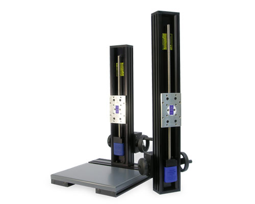
Side Knob BiSlide Assembly
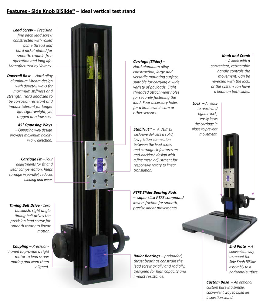
The configuration of the Side Knob BiSlide positioning stage makes an ideal precision vertical test stand. In addition, the Side Knob BiSlide can be used for many other applications where a vertical positioning stage may be useful, such as positioning a laser or a camera.
tab=0Overviewtab=1Featurestab=2Model / Seriestab=3Specificationstab=4Options / Accessoriestab=5Downloadstab=6Examplestab=7Troubleshooting / FAQs
The Side Knob BiSlide delivers effective rotary to linear motion by using a right angle timing belt drive connected to a fine pitch lead screw. The motion allows the slide to move a payload up and down into position smoothly and precisely.
Constructed with hard-coat anodized, aluminum dovetail ways and smooth motion PTFE bearings; BiSlide Assemblies deliver higher rigidity for longer life and more precise movement. The manually-operated Side Knob Assembly has a peak load capacity of 40 lbs. (18.1 kg.) Three typical test stand travel heights are available – 5, 10 and 15 inches (12.7, 25.4 and 38.1 cm respectively) – or a custom height Side Knob BiSlide can be designed.
Side Knob BiSlide® Features
Because the Side Knob is a configuration of the linear Velmex BiSlide Assemblies, it has many of the same features and benefits found on the world-recognized BiSlide stages.
Side Knob BiSlide® Style Options
Part number information for each style can be found under Specifications at the end of the page.
|
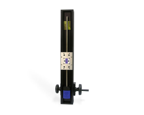
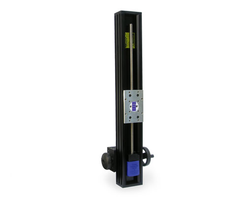
The Side Knob BiSlide Assembly has three style options based on the mounting of the Knob and Lock: |
|
• Mounting – Lock Left / Knob Right Pictured is the Lock Left / Knob Right |
||
Please refer to either manually-operated or motor-driven BiSlide Assemblies for additional details, specifications and examples of other BiSlide models, series and styles.
Side Knob BiSlide® Specifications
Factors such as size of the motor, size of the payload, travel distance, mounting direction/plane, etc. effect the actual capability of any assembly. Please contact Velmex Application Engineers to configure a system that will meet your exact requirements.
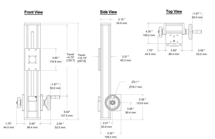
Side Knob BiSlide Assemblies are available in 3 standard vertical travel distances – 5, 10 and 15 inches (12.7, 25.4 and 38.1 cm respectively).
| BiSlide® | Travel Distance | Base Length | Slider Length | ||||
| Series | Inches* | cm | Inches | cm | Inches | cm | |
| MN10 – Side Knob (All styles) | |
5" - 15" | 12.7 – 38.1 | (Height) 15.15" – 25.15" | 38.48 – 63.88 | 5" | 12.7 |
* Standard is up to 15" in increments of 5", but it is possible to go to a maximum of 40".
| BiSlide® | Weight | Height | Width | ||||
| Series | lbs. | kg. | Inches | cm | Inches | cm | |
| MN10 – Side Knob (All styles) | |
7.4 – 11 (without base) | 3.4 – 5 | 15.15" – 25.15" | 38.48 – 63.88 | 7.24" (depth 4.6") | 18.4 (11.68) |
| BiSlide® | Dynamic Load | Static Load | Momentary Load | |||
| Load Capacity | lbs. | kg. | lbs. | kg. | lbs. | kg. |
| Lift (maximum) | 40 lbs. | 18.14 | 40 lbs. | 18.14 | 100 lbs. | 45.36 |
| Coefficient of friction | 0.09 typical |
| Repeatability | 0.00015" (4 microns) typical |
| Straight line accuracy | 0.003"(0.076 mm) over entire travel distance. Higher accuracy 0.0015" (0.038mm) available |
| Screw lead accuracy | 0.003"/10" (0.076 mm/25 cm) 0.0015"/10" available. Consult factory. |
| Operating temperature | 0 to 180° F (-18 to 82° C) |
| Properties of Velmex Stages | Information on stage composition, tolerances, wear and design for specialty applications. |
BiSlide® Dimensions |
||
|---|---|---|
 |
||
| Carriage | ||
 |
||
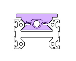
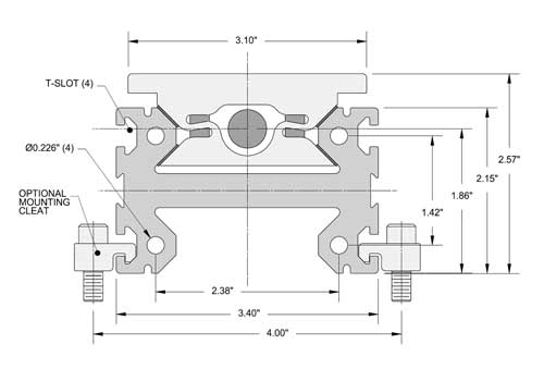
BiSlide Base Cross-Section
The slider / carriage (shaded area in the cross-section to the left) rides inside the guide ways. The 45 degree opposing ways give strength to carry the payload.
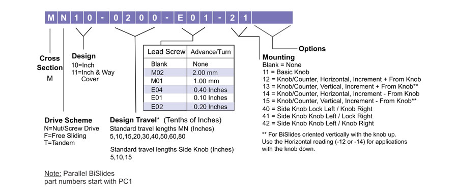
All BiSlides have the same basic part number configuration. The number varies with the series, the travel distance, the lead screw and the motor mountings. Additional prefixes and suffixes are added for the options and accessories. You can determine the BiSlide part number using the chart below. Side Knob part numbers end in 40, 41 or 42.
 |
![]() BiSlide Assemblies conform to European Machinery Directive (89/392/EEC) Annex 1
BiSlide Assemblies conform to European Machinery Directive (89/392/EEC) Annex 1
Options/Accessories for Velmex Side Knob BiSlides®
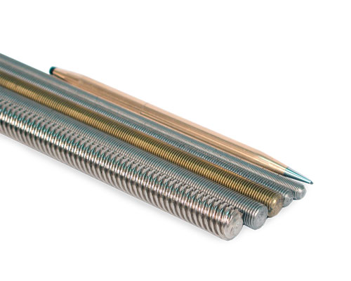 |
Alternative Lead Screws – The Side Knob BiSlide is standard with an E01 leadscrew (0.1" advance per revolution). Alternative lead screws are available as options. |
|
|
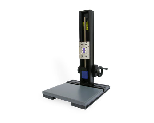
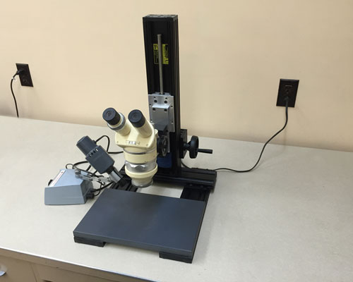
Mounting Base – Optional mounting base provides the Side Knob BiSlide assembly the perfect platform for an inspection station. |
|
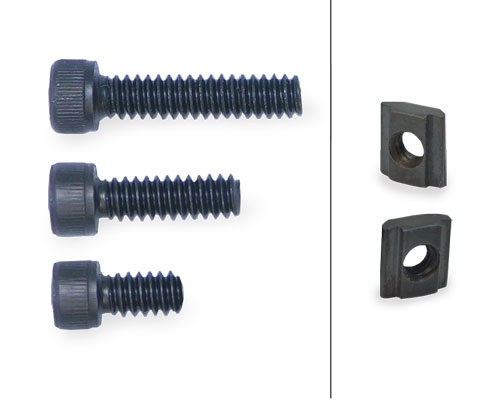 |
T-Nuts , mounting bolts and other hardware – to create strong, secure attachments. Can also be used with the cleats. For more information on BiSlide hardware visit the BiSlide Adapters page. |
|
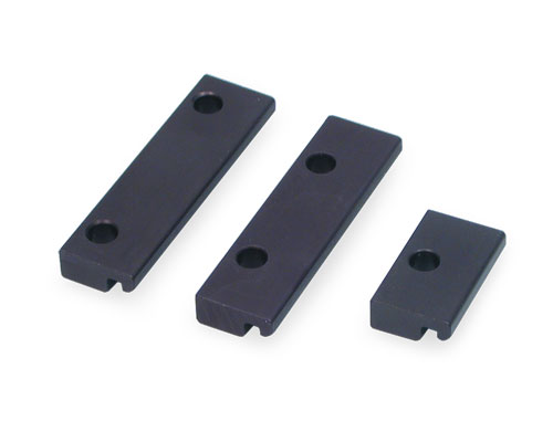 |
Cleats - use BiSlide cleats to create rigid XY attachments, mountings for optical tables and attachments to other T-slot framing systems. The cleats are also used to secure BiSlides for longer travel distances and to support larger loads. For more information on BiSlide hardware visit the BiSlide Adapters page. |
|
MC-1 – Standard 1 hole cleat. Mounts the BiSlide to a frame / base / surface. Can be used to mount to other BiSlides in an XY, XZ or XYZ configuration. |
||
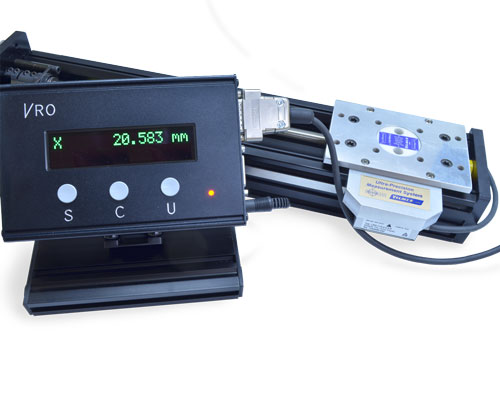 |
Encoders and VRO™ Encoder Readout – For a high resolution position readout an encoder and Velmex's VRO encoder readout can be mounted to the linear slides. An encoder, mounted directly to the slider gives a true and accurate reading eliminating lead screw and backlash errors. The VRO is compatible with all 5V incremental encoders. Fully functional, it features automatic memory back-up of settings, sleep mode and self diagnostics. It’s highly visible, wide-screen LED display makes it easy to view the positioning results. SEE: Velmex Controls on the Encoders and the VRO Readout for additional details. |
|
For .STP files, you may need to right click on the download button and save the "target" or "link".
| Click to open the section you need: | "Right Click" to download. |
The majority of CAD drawing found in our Technical Library are Step (.stp) files. You will also see .dxf, .dwg, .sat and .pdf files. If you require a different format or cannot located the drawing you require, please contact us. Drawings are identified by the series/model part no. The number can be found on the side or end of any Velmex device you may already own.
| Series | Type | File Name | Description | Download | View |
|---|---|---|---|---|---|
| MN10 - Lock Left / Knob Right | STP | MN10-0050-xxx-40 Side Knob.stp | Side Knob BiSlide, Lead screw, 5" Vertical Travel, - lock left,/knob right |
- | |
| MN10 - Lock Left / Knob Right | STP | MN10-0100-xxx-40 Side Knob.stp | Side Knob BiSlide, Lead screw, 10" VerticalTravel - lock left / knob right |
- | |
| MN10 - Lock Left / Knob Right | STP | MN10-0150-xxx-40 Side Knob.stp | Side Knob BiSlide, Lead screw, 15" Vertical Travel, - lock left,/knob right |
- | |
| MN10 - Knob Left / Lock Right | STP | MN10-0150-xxx-41 Side Knob.stp | Side Knob BiSlide, Lead screw, 15" VerticalTravel - knob left / lock right |
- | |
| MN10 - Lock Left / Knob Righ | STP | MN10-0200-xxx-42 Side Knob.stp | Side Knob BiSlide, Lead screw,, 20" VerticalTravel - knob left / knob right |
- | |
| MN10 - Knob Left / Lock Right | STP | BiSlide_Side_Knob_Left_30 inch.stp | Side Knob BiSlide, Lead screw, 30" VerticalTravel - knob left / lock right |
- |
Side Knob BiSlide Documents
| Type | File Name | Description | Download | View |
|---|---|---|---|---|
| BiSlide Side Knob Info Sheet.pdf | Side Knob BiSlide information Sheet with specifications | |||
| Side Kob BiSlide Dimensional Drawings.pdf | Dimensional drawings for the Side Knob BiSlide |
Velmex Side Knob BiSlide® Applications and Examples
These are examples of Velmex products. If you wish a similar product, please contact us with your specific application specifications (travel distance, payload, hours per day in use, resolution, speed range, etc.). You can use the Request Assistance form. |
Pictured in our gallery are examples of several configurations for the Side Knob BiSlide. Product and accessory offering is subject to change and availability.
| Example Key Code | Meaning | Example Key Code | Meaning |
|---|---|---|---|
| A | Manually Operated | M | Motorized |
| S | Standard | C | Custom Configuration |
| B | BiSlide | U | UniSlide |
| X | XSlide | R | Rotary Tables |
| T | XY Tables | TT | Turntables |
| E | Elevating Tables | FS | Fun Stuff (Ingenious, Cool, or Just out of the ordinary applications) |
|
|
Sorry, we don't have any images of our Side Knob BiSlides used with other BiSlides in a system. Please check back later.
Sorry, we don't have any images of a system using our Side Knob BiSlides and other Velmex stages. Please check back later.
|
|
Examples of other Velmex products can be found on the Examples page or in the Examples section for each product.
Many questions can be answered by reviewing the "Features", "Model / Series", "Specifications", "Options / Accessories" and "Technical Documentation" sections for each product line. Additional FAQs about product comparisons, product construction, purchasing and shipping can be found on the company FAQ page.
Do BiSlides need lubrication and how often?
Lubrication is important for motor-driven systems or wherever you want maximum life and the lowest friction. BiSlide Assemblies should be lubricated with Velmex BL-1 oil. Only a few drops are required to keep your slide running smoothly. The load and hours of use effect the amount and frequency of lubrication. Manual BiSlide assemblies require less frequent lubrication. See the user guide that came with your BiSlide for recommendations.
Can BiSlides be mounted together?
Yes, BiSlides can be mounted together in XY, XZ, XYZ configurations. However, Side Knob BiSlide stages because of the knob control design are usually operated as stand alone positioners. You rarely will find them incorporated in other system designs.
How do you adjust the carriage fit on an BSlide?
Adjustments the carriage on a BiSlide may be necessary after break in period and less frequently thereafter. The Lead Screw Nut (StabilNut) has an adjustable mesh to minimize backlash. Carriage fit can be adjusted by tightening the bolts on the carriage surface. See the BiSlide Owners Manual for how and when to adjust
If you have questions about your specific application or want us to design a Side Knob BiSlide System for you, please complete the Request Assistance form or call Velmex to speak to one of our Application Engineers.