
Velmex FAQs
The following are commonly asked questions about our company and our products.
Velmex Linear Stages
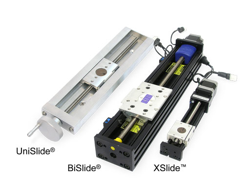
| UniSlide® | BiSlide® | XSlide™ | |
|---|---|---|---|
| Summary | Versatile. More choices in sizes, screw pitches, etc. - Manually-operated or motor-driven. | Improved cantilevered load performance. Longer travel distances Highly configurable with frames and bases. - Manually-operated or motor-driven. | Smaller, more compact. Cost effective. - Manually-operated or motor-driven. |
| Size | 5 different size cross sections from 1.5" wide to 9" wide | 3.4" W x 2.5" H | 1.9" W x 1.2"H |
| Slider Length | 1.5" - 12" (3.1 to 30.5 cm) | 4.6" (11.7 cm) | 2" (5.1 cm) |
| Load Capacity | Depends on the series. Horizontal up to 400 lbs / 180 kg - Vertical up to 100 lbs / 45 kg | Horizontal 300 lbs /135 kg Vertical 100 lbs /4 5 kg | Horizontal 35 lbs / 15 kg Vertical 10 lbs / 4.5 kg |
| Maximum Travel Distance | 42" / 107 cm | 228" / 579 cm (5.8 m) | 30.5" / 77.5 cm |
| Conversion to Multi-Axis Systems | Uses adapters and brackets. | Uses cleats. Easy to configure. More versatile. | Uses cleats. Easy to configure. |
| Lead Screw | 7 screw pitches in two accuracy grades. | 5 screw pitches in 2 accuracy grades. Optional: High speed belt drive. | 7 screw pitches in 2 accuracy grades. |
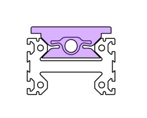
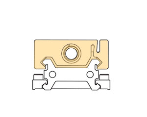
| Ways / Slider | Dovetail ways. Slider rides inside the guide ways. | 45 degree opposing dovetail ways and a strong I-beam profile. Slider rides inside the guide ways. | 45 degree opposing dovetail ways. Slider rides on the outside of the guide ways. |
| Slider Profile | 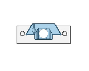 |
 |
 |
| Finish | Standard: No finish - base aluminum Optional: Hard coat black anodized, or nickel-plated | Hard Coat Black Anodized | Hard Coat Black Anodized |
Cross Sections – The cross sections of the Velmex linear stages are a key differentiation. While the three Velmex linear stages all have bases with dovetail ways, they each have a different cross-section profile. (images above) The sliders (carriages) each ride on the ways differently.
Our smallest models are all Free Sliding manually-operated models.
• The smallest BiSlide Assembly has a travel distance of 5", a base length of 12.95" and a base width of 3.4".
• The smallest UniSlide Assembly would be in the A15 Series with a travel distance of 1.5", a base length of 3" and a base width of 1.5".
• The smallest XSlide Assembly has a travel distance of 2.5", a base length of 11.1" and a base width of 1.9".
• The smallest XY Table is a manual AXY2506 UniSlide tabe which has a travel distance of 2" by 2".
• The smallest Elevating Table is an A39 series UniSlide which has a vertical travel distance of 1".
• The smallest rotating table is a model A2505TS Turntable which is 3.15" in diameter.
The smallest motorized models would have the same travel distances reported above, but the overall length would be longer depending on the motor used.
We have made assemblies with travel distances shorter than our standard offering. Please contact us with your specifications, if you require a shorter travel distance.
The longest BiSlide would be a belt-drive model with a travel distance of 228", a base length of 245.3" (without the motor) and a width of 7.24". The longest lead screw model has a travel distance of 80", a base length of 90.35" (without the motor) and a width of 3.4".
The longest UniSlide Assembly is an A60 Series with a travel distance of 41", a base length of 48" (without the motor) and a width of 6".
The longest lead screw XSlide model has a travel distance of 30", a base length (without the motor) of 34.05" and a width of 1.39".
As a standard, we use the machine tool coordinate designations where 'X' is the bottom horizontal axis, 'Y' crosses the 'X' at 90 degrees and is also in the horizontal plane, and the 'Z' axis runs vertically (perpendicular) to the 'X' or 'Y' axis.
An XY configuration can be turned and used in the vertical plane. If this is done, the horizontal load specifications no longer apply. Review vertical load specifications when using a stage with the axes this way.
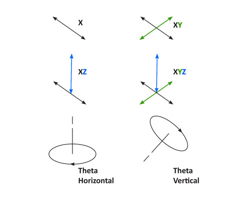
A load in the X or the Y plane is usually travelling horizontally. The slides are also oriented horizontally, however they can be positioned upright, inverted or on their edge/side. With the Z axis the slide is oriented vertically and the load is usually travelling vertically or up and down.
Most Velmex linear stages can be mounted on their ends and used as a stand alone Z axis. The load in this case is often considered a cantilever load. When mounted in combination with multiple stages in X or XY axis other factors need to be considered to calculate load including the weight of all the components. Which assembly and the dovetail profile of the carriage can also make a difference in the load the slide can carry. (See the load questions below.)
Yes, all Velmex stages can be used in either the vertical (Z) or inverted X or Y position. However, inverting the stage puts restrictions on the load it can carriage. See the FAQ that follows on loads and how to calculated the permissible load.
Most Velmex linear stages can be mounted to other stages in the same product line in XY, XZ, XYZ configurations. They also can be combined with Velmex Rotary Tables and our other linear stages to make custom systems to meet a wide range of requirements and applications.
• Mounting UniSlide assemblies in multi-axis systems requires the use of adapter plates and brackets. See UniSlide Options and Accessories for more information on the plates and adapters.
- You need to disassemble an A15 Series UniSlide in order to mount it on to a surface or another slide. Please follow our Disassemble A15 Series Instructions. Other UniSlides, BiSlides and XSlides do not need to be disassembled to access the mounting holes.
• Mounting BiSlide assemblies in multi-axis systems is easy using cleats. T-slot bases and frames can be added for more structure and to create application specific systems. TSee BiSlide Options and Accessories for more information on the cleats and T-slot structuring. XSlides can be easily mounted in an XY configuration with the use of XSlide XMC-2 cleats.
• XSlides can be mounted in an XZ or XYZ configuration using XMB-2 bolts or a gusset can be added for more rigidity. See XSlide Options and Accessories for more information on the cleats and T-slot structuring.
Velmex has several thousand standard configurations of linear slides when you include the options, accessories and the multitude of sizes. However, our standard offering does not always meet every requirement. Our sales application engineers can design a custom solution to meet a customer's specification. Custom systems could include design, mounting and testing charges; and contain custom, externally-fabricated components.
Many factors influence the payload any individual stage can accommodate effectively. They include duty cycle, speed in the case of motorized stages, orientation of the payload, and orientation of the stage. The basic definitions follow:
The Normal Load is the recommended range for continuous duty or moving the carriage with a payload on board. It may also be referred to as "Dynamic Load". This is the range the stage should be operated in for optimum performance, longer assembly life and safety.
Maximum load is the absolute top (permissible) range that the stage has been rated to handle with the payload centered on the horizontal axis in the upright position. It sometimes is referred to as "Static Load". If you are working with the stage at the maximum load, it is recommended the payload be placed on the carriage after the carriage (slider) has been moved to the position required. The payload should be removed before the carriage is moved again.
Another load term you may see is "Momentary" (think of as impact). This is when the load is placed or brought down on the slide for a very short duration. It is a factor that might be in an assembly line process.
All of the above assume a single axis stage. You also need to consider the number of axes in the system. If it entails more than one axis, the weight and orientation of each subsequent stage and any required adapter plates or gussets need to be considered. Combining slides or rotary tables in XY or XYZ configurations can create a cantilever load. In these configurations the X axis carries the weight of the Y axis and/or Z axis (and/or theta axis), any components and the attached payload.
Additional design factors can be incorporated to accommodate larger payloads such as going up in stage size, adding additional carriages to the slide, or looking at tandem or parallel Velmex slides.
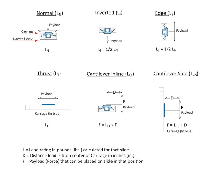
Load calculations for Maximum and Normal (in Horizontal Center and Vertical Center), along with Load Thrust and Cantilevered Loads are found under the specifications for each brand of Velmex stages.
Loads are calculated for one independent axis in the stated orientation. Additional factors need to be considered when it is a multi-axis configuration.
Cantilever loads and the load on the stage when mounted inverted or on the stage's side are also affected by gravitational forces that pull the payload and the carriage down. The rating for a Cantilever type load is always going to be less than that of a normal load. How to calculate the allowable load and illustrations of each follow. The profile of the carriage and the dovetail way the carriage is nested in also affects the tensile strength the stage has to support the weight of the payload when placed in a cantilever, suspended (gantry) or inverted position. Depicted below is the load calculation for Velmex UniSlide Linear Assemblies.
 |
||
|---|---|---|
Velmex Slide Composition
Velmex products are primarily manufactured from hard-alloy aluminum. Lead screws are either 303 stainless steel or nickel-plated steel depending on the pitch. The BiSlide and XSlide assemblies have black anodized bases. Black anodizing is an option for UniSlides. They also can be hard coat anodized or nickel-plated for an additional charge.
Other finishes are available. Please contact one of our application sales engineers to find out what finishes are available to your needs.
For additional information on stage composition, tolerances, wear and design for specialty applications, please refer to Properties of Velmex Stages.
No, we cannot provide our stages in stainless steel. Our products are precision machined for accuracy. Machining stainless steel is very difficult because of the hardness of the material, it the process more costly.
Anodizing delivers the similar characteristics to stainless such as surface hardness and abrasion, corrosion or chemical resistance. And they are also lighter in weight the comparable stainless steel stages.
Yes, Velmex slides are RoHS compliant. See the ROHS Declaration of EU RoHS2 Compliance.
BiSlide assemblies can easily be converted from a manually-operated slide to a motorized version. See the BiSlide Owners Manual for the instructions on converting the stage. UniSlides, XSlides and Velmex Rotary Tables cannot be converted. You should purchase the version you require at the onset. It is possible, however, to buy Velmex stages pre-configured for both manual and motorized operation with a double shaft stepper motor.
Options and accessories like revolution counters can be added to Velmex assemblies after the fact. However, because of special adjustments, possible cutting or turning and additional hardware that may be required, the assembly needs to be returned to the factory to properly fit the additional component. There is a nominal charge for reconfiguring assemblies.
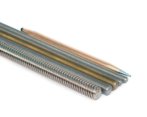 Velmex does not purchase lead screws from external sources. We manufacture our own, which gives us more control over the quality. Each screw is rolled through precision dies, delivering high quality and accuracy.
The lead screws are comprised of either 303 stainless steel or electroless nickel-plated, cold-rolled steel. The linear accuracy of our standard lead screws is 0.007" / 10" of length or less. The linear accuracy of our precision lead screws is 0.0015" / 10" or 0.033 mm / 20 cm of length.
We have the additional capability of combining left- and right-hand threads on a single shaft for together and apart movement of two payloads. This is useful in applications where two objects must share a common axis of movement. They separate and return to center with one control.
The UniSlide Line also has two independent-driven sliders on a common base. The movement of the sliders are independent from each other. They can move in the same direction or opposite directions through two control knobs at each end of the base. Available only in manually-operated configurations.
Velmex lead screws are standard in all Velmex linear positioning devices. They can also be purchased separately.
Below is a chart showing the available lead screws and pitches. Followed by the lead screw code for each Velmex brand. The code can be found after the base lengthin the model number. See the Model Number explanation that follows.
| Pitch | Diameter | UniSlide® Letter Code | BiSlide® Code | XSlide™ Code | |||||
|---|---|---|---|---|---|---|---|---|---|
| Turns per inch | English Thread Lead Screws | Advance per revolution | Screw Drive Model |
Graduated Knob Model | Standard | Standard** | |||
| 0.25" | 0.375" | 0.50" | |||||||
| 2.5 * | no | yes | yes | 0.400" | W4 | P2.5 | E04 | E04 | |
| 5 * | no | yes | yes | 0.200" | W2 | P5 | E02 | E02 | |
| 10 | no | yes | yes | 0.100" | W1 | P10 | E01 | E01 | |
| 20 | yes | yes | yes | 0.050" | B | P20 | -- | E50 | |
| 40 | yes | yes | yes | 0.025" | C | P40 | -- | E25 | |
| Maximum length available | 3 ft. | 8 ft. | 8 ft. | 42" | 18" | 80" | 30" | ||
| Turns per centimeter | Metric Thread Lead Screws | Advance per revolution | Screw Drive Model |
Graduated Knob Model | Standard | Standard** | |||
| 7 mm | 10 mm | 14 mm | |||||||
| 5 | yes | yes | yes | 2 mm | K2 | Q2 | M02 | M02 | |
| 10 | yes | yes | yes | 1 mm | K1 | Q1 | M01 | M01 | |
| Maximum length available | 3 ft. | 8 ft. | 8 ft. | 42" | 18" | 80" | 30" | ||
* Not recommended for vertical units because it will back drive.
* * More accurate screws are optional.
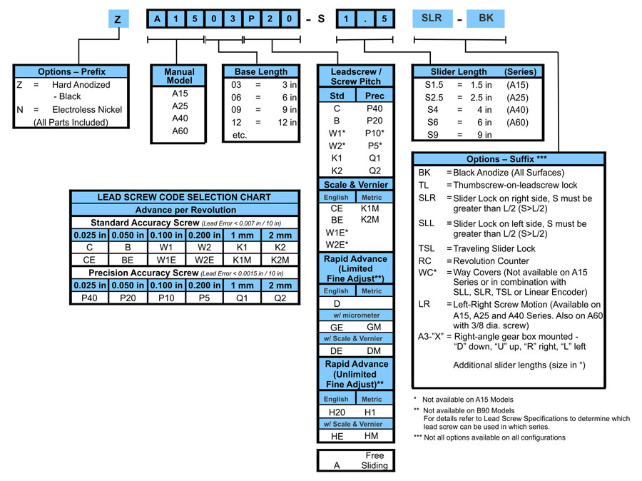
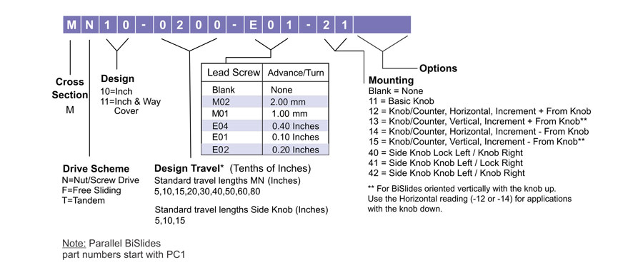
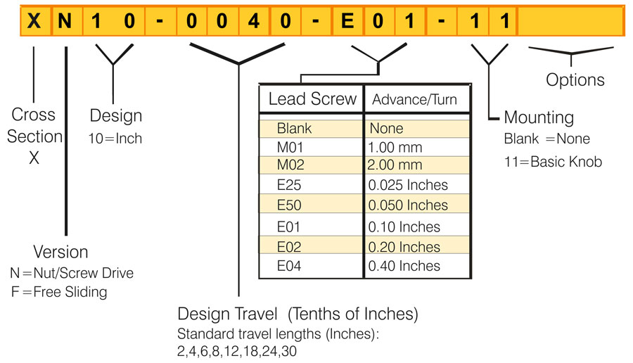
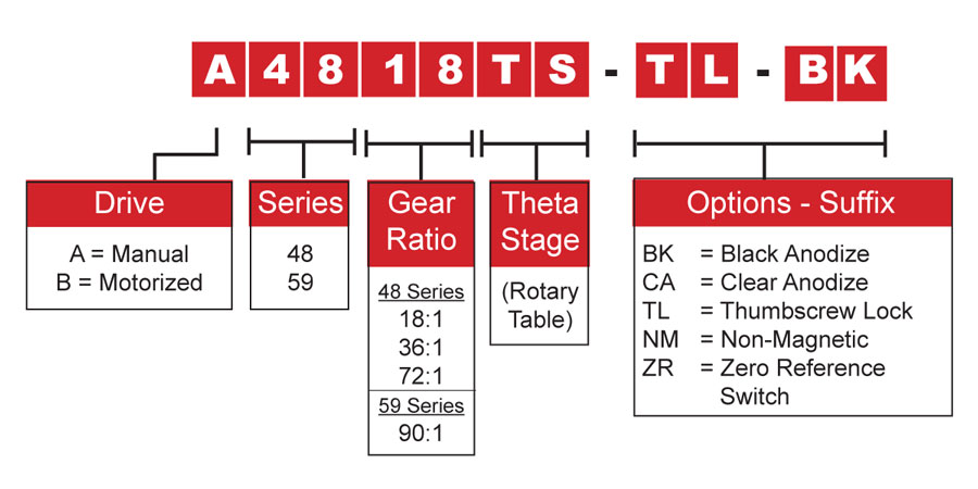
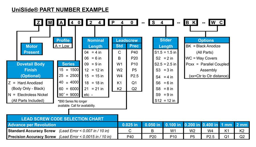
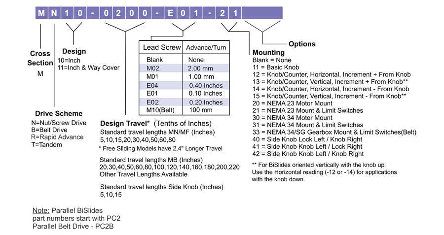
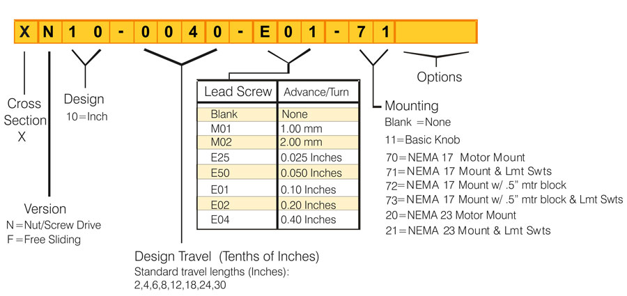
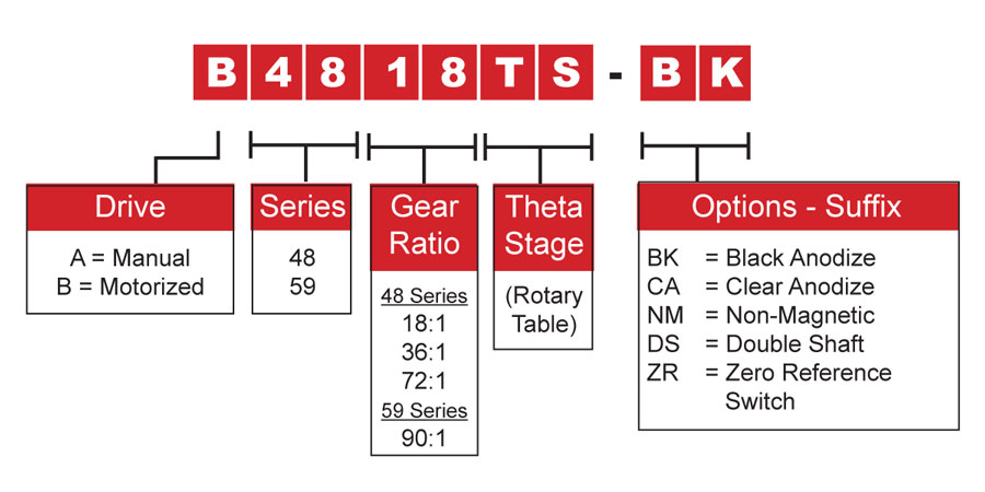
The codes generally represent the series or drive configuration, the travel distance, the pitch / advance of the lead screw and any mounted option or accessory. For the specific model breakdown, please refer to the schema below.
- Manually-Operated Products
- Motorized Products
Manual UniSlide® Assemblies
Manual BiSlide® Assemblies
Manual XSlide™ Assemblies
Velmex Rotary Tables
Motorized UniSlide® Assemblies
Motorized BiSlide® Assemblies
Motorized XSlide™ Assemblies
Motorized Rotary Table Assemblies
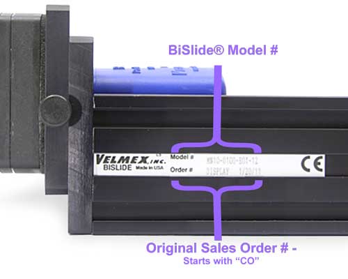
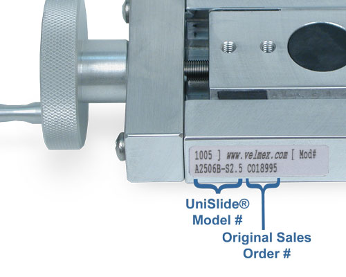
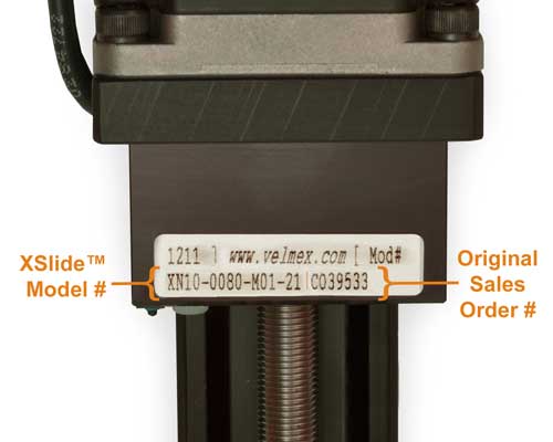
The model/part number is usually located on the side or end of the stage or table.
 |
 |
 |
|---|
Use of Velmex Positioners
Velmex products are used in many industries for a variety of applications. Both manual and motorized versions are used in single and multiple axes configurations. A few examples:
• Velmex stages have successfully been used in environments including: clean rooms; outdoors; underwater; in a vacuum; attached to aircraft; on naval ships; and in outer space.
• Instrumentation and Laboratory Equipment
Testing machines; dimensional quality control testers; compression and tension testing machines; air and fluid positive displacement systems; probe and transducer positioning; wind tunnel testing; air entrainment in concrete test equipment; soil mechanics test apparatus; ring engraving machines; ophthalmic instruments; chemical sampling and handling equipment; microscope and telescope positioning; viscometer apparatus. . .• Environmental Research
Plant and animal tissue measurements; shellfish and tree ring non-contact measurements; even counting gnats on figs in Kenya.• Medical Devices
X-ray and MRI positioning; scanning; fiber optics arrays for cancer research; radiation therapy research; respiratory simulation. . .• Electro-optics / Photonics
Stop motion animation; laser positioning; optical scanning; holographic imaging,; light source and optical element positioning; spectrometer and spectroscopic equipment; testing photo transducers; CRT illumination and magnetic field measuring; LCD, LED, VFD, illumination testing; 3D imaging; optical fiber locating; lens and mirror polishing equipment; digital, film and video camera positioning; photometer and radiometer positioning; film imaging alignment equipment. . .• Electronics Production and Testing Wafer handling; inspection equipment automated machinery; component pick and place; crystal growing equipment; antenna positioning; training devices and simulators; cleaving equipment. . .
• Metal, Glass, Rubber, Plastic and Wood Fabrication / Workhold Equipment
Drilling fixtures; laser welding; engraving machines; soft material slitting and sawing machines; rubber and plastic dipping; adhesive disposition; gauging and measurement; punch press backstop adjustments; welding head positioning; furniture routers; small parts grinding machinery; packaging machinery; glass and tube machinery; tire manufacturing machinery. . .
Yes, Velmex products can be used in vacuum or specialty environments with modifications or material substitutions. What is required depends on the environment. For more information on material substitutions, outgassing and other environmental considerations, please check the Vacuum Environments page.
Slide/Stage Maintenance
Lubrication is important for motor-driven systems or wherever you want maximum life and the lowest friction. Only a few drops are required to keep your device running smoothly. The load and hours of use effect the amount and frequency of lubrication. See the user guide that came with your Velmex device for recommendations.
• UniSlide Assemblies can be lubricated with Velmex BL-2 oil.
• BiSlide Assemblies should be lubricated with Velmex BL-2 oil.
• XSlide Assemblies can operate without lubrication. Under severe duty applications Velmex BL-2 oil can reduce friction and minimize wear.
• Normally, the worm gear drive of Velmex rotary tables do not need any servicing. However, under severe conditions replenishing the lubricant will prolong the life of the gears. A small amount of Lubriplate can be placed in the access hole.
See the product's Owners Manual for specifics on how and when to adjust.
• An adjustable expansion gib controls the fit of the UniSlide carriage. Adjust by tightening the Allen head screws located at the end of the slider.
• Adjustments on the carriage on a BiSlide may be necessary after break in period and less frequently thereafter. The Lead Screw Nut (StabilNut™) has an adjustable mesh to minimize backlash. Carriage fit can be adjusted by tightening the bolts on the carriage surface.
• On an XSlide carriage, all fine tuning/wear compensation can be easily accomplished without removing a payload from the slide. Both the carriage fit and the lead screw / nut mesh adjustments are accessible from the sides of the slider. No need to remove the payload.
Yes, the drive nut tension can be adjusted all Velmex linear slides. An adjustable mesh minimize backlash on each of the drive nuts. Refer to the product Owner's Manual for instructions and frequency.
• UniSlides and XSlides use a tension adjustable drive nut made of Delrin AF®. The UniSlide has one adjustment location the top of the drive nut. The XSlide adjustment in located from the side of the slider.
• BiSlide uses a Velmex exclusive StabilNut™ comprised of a low friction polymer. There are two adjustment locations in the top of the drive nut.
No, the thrust bearings on the majority of Velmex linear stages are pre-sealed and do not require any additional lubrication or maintenance.
Motor FAQs
- For incremental positioning or scanning when computer-controlled motion is desired.
- For complex motion requirements of more than one distance and/or speed; fast or slow starts/stops, and fast reversing.
- When accurate speeds are required.
- For speed range requirements as high as 1 to 6000 steps/sec.
- When a brushless motor is required.
Step motors are very common in linear positioning because of their ability to operate within very precisely defined increments. They work efficiently when there is frictional load to dampen them. Velmex assemblies have friction, and a polymer lead screw drive nut which absorbs step vibration. Velmex lead screws have low inertia relative to the motor inertia, making very fast accelerations and decelerations possible. Step motors reach full torque in just one step.
Step motors, when controlled with Velmex Controllers, do not miss or lose steps. Step motors run synchronously to their phase switching speed. When an external motor load exceeds the running torque of the motor, the motor may stall and lose a position greater than one step.
Velmex step motor controllers remove the problems of low speed motor resonance by utilizing half-stepping and controlling the current. The VXM switches the motor drive amplifiers directly, eliminating the sensitive pulse to motor translator link.
Proper motor sizing and operating the motor in a range that provides a torque reserve will ensure reliable operation. Review the motor speed/torque curves to determine the maximum reliable operating speed. Our Sales Application Engineers can help you determine the right motor size to operate the Velmex slide efficiently and effectively.
Depending on the situation, the system may sound different than it does under normal operation. The following are some sound bytes to help troubleshoot motor and controller operation.
| Description | Sound |
|---|---|
| The sound of a normal operating stepper motor: | |
| The sound of an overloaded motor: | |
| The sound of a motor when acceleration is set too high: | |
| The sound of a motor when the speed is set too high: | |
| The sound of a motor with a broken wire: |
VXM™ Controller FAQs
Yes, VXM configurations can control up to 4 motors, 1 motor at a time. The VXM-4 System can handle 4 motors and consists of 2 linked VXM Boxes. Two motors can also be controlled simultaneously with the VXM1-1. See the Controllers Page for more details and specifications.
In order to program the VXM Controller for your specific application, it should be connected to a PC, Laptop, Tablet or PLC. However, the VXM-1J Control has a simple jog and auto-reverse functioning and does not require a computer to program.
Yes, if you have your own motors and controllers, you can use them with Velmex motor-ready products. The VXM Controller, however, has been specifically designed to optimize stepper motor control. Its a very dependable and low cost solution for high precision positioning requirements.
The Velmex VXM for step and direction has been designed to work with other motors, specifically motors with built-in controllers, if the motor can take step pulses. With this VXM version, you gain "smart control" of the motor. .
Velmex motorized stages, motors and the VXM Motor Controller come as a complete system, ready to plug in. See the Controllers Page for more details and specifications.
The default speed of the VXM Controller is 2,000 steps per second.
It is not recommended. An Arduino cannot generate enough torque to allow the motor to operate within the normal speed ranges.
Encoder FAQs
Yes, encoders can be used to determine payload positions on Velmex slides and tables. We offer inductive and magnetic encoders for UniSlide and BiSlide linear stages and rotary encoders for the Rotary Tables and the compact XSlide. You would also need a readout like the VRO™ to interpret the data being transmitted by the Encoder.
Because the carriage rides on the outside of the ways as opposed to the inside it's difficult to tell where the carriage is positioned in relation to the travel distance. A rotary encoder fixed to the lead screw at the end of the XSlide is a better solution.
Yes, Velmex offers an number of options in addition to the linear and rotary encoders to measure travel. In most cases, these options would be used with manually-operated stages. They include:
- A lithograph scale attached to the base and index pointer attached to the carriage.
- A mechanical revolution counter
- Scale and vernier
- A graduated knob with precision grade lead screws (our most popular option)
- A micrometer head
To see which is measuring option is available for which Velmex product, check out that Product's Options and Accessories found on each Product Page.
VRO™ Readout FAQs
The VRO can provide a readout from linear and rotary encoders for one or two axes. The axes can be configured in X, XY and XZ. An XYZ or other multi-axis configuration would require additional VRO Readouts.
The VRO was designed for differential type encoders, however, it is fully compatible with single-ended encoders.
The VRO can report position in either Imperial English or metric. It can count revolutions. It also can report in degrees when connected to a rotary encoder.
Purchasing Velmex Products
Velmex has over 4,000 possible sizes and configurations of linear and rotary stages. Please contact one of our Application Sales Engineers about your needs and your product specification requirements. They can aid you in selecting the proper stage and configuration at the lowest cost.
You can start the process by completing our on-line Request Assistance form which will help us envision what you are interested in. You are also welcome to call - 1-800-642-6446 or +1-585-657-6151.
Because we build every stage to order, we prefer to have the customer's requirements before we quote a price. Since we do not have an on-line store, pricing is not available on our website.
Our pricing is structured to provide the most cost effective solutions to Educational Institutions and Government Organizations. However, we do offer quantity discounts.
We build every Velmex product to order. A typical lead time is 2 to 3 weeks after receipt of the order for standard products. Custom configurations will usually take longer. Please contact us for a precise lead time.
We manufacture all Velmex products in our facilities in upstate New York. You can buy direct through us or through one of our international distributors. We ship worldwide.
Replacement parts are available direct from us. Call us or complete our Request Assistance form.