


|
|---|
UniSlide Manual Linear Motion Products
Manually-Operated Velmex UniSlide® Systems are available in a variety of configurations, models and sizes including Linear Slide Assemblies, Elevating Tables and XY Tables. Specialized UniSlide systems including our TA Measurement System for Tree Ring Analysis and Petrographics Analysis for Concrete are also available.
tab=0Overviewtab=1Featurestab=2Model / Seriestab=3Specificationstab=4Options / Accessoriestab=5Downloadstab=6Examplestab=7Troubleshooting / FAQs
Manual UniSlide® Assemblies Overview
Velmex UniSlide Assemblies are available in manually-operated and motor-driven models to meet a wide range of applications when reliable, precise linear motion is a requirement. UniSlide stages are compact, delivering maximum travel in the shortest amount of work space. Their modular design allows for easy construction of multi-axis systems.
There are five manual series of Linear UniSlide Assemblies. Configurations include Free Sliding, Screw Drive, Rapid and Fine Motion; Graduated Knob and Scale with Vernier. Left-Right Screw Motion UniSlide systems feature two carriages (sliders) and are ideal for applications where two load objects must share a common axis of movement. Standard travel distances of Velmex Manual Linear UniSlide systems range from 1.5" (3.81 cm) to 42" (106.7 cm). There are three manual series of XY Tables. There are four series of Elevating Tables. UniSlide Elevating Tables and UniSlide XY Tables can lift up to 100 lbs. (45.5 kg.).
UniSlide Linear Slide Assemblies, XY Tables, Elevating Tables and Velmex Rotary Tables can be combined for an infinite selection of custom configurations. Note: Manual UniSlides cannot be converted to motorized. They would need to be returned to the factory for conversion. Purchase a motor-ready version to add a separately purchased motor.
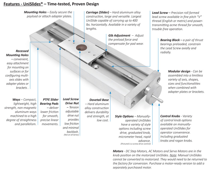
UniSlide® Features
UniSlide Applications
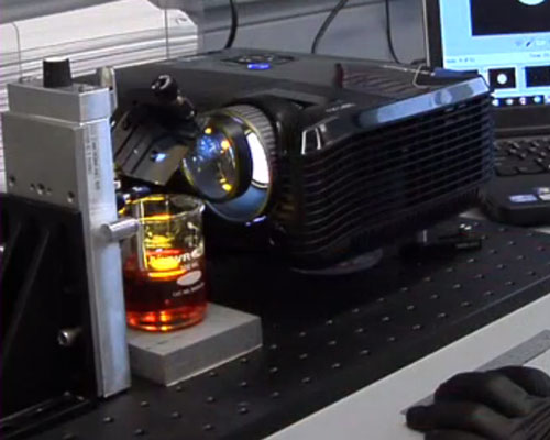
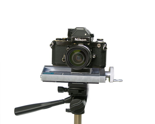
The UniSlide Stage's highly flexible, yet simple, reliable design makes it ideal for instrumentation and measurement; alignment, inspection and QA/QC; optical focusing; antenna alignment; film and animation work; medical and biological analysis. In addition it can be used for moving probes, sensors, components; light machining; semiconductor and electronic component manufacturing; or any application where resolution in the micron range is required.
UniSlide® Manually-Operated Series / Style
Standard UniSlide Assemblies are configured as linear stages, elevating tables and XY tables. UniSlide Linear Assemblies consist of five Series with varying body widths. Visit the individual pages for each Series for more specific information.
Linear Series
Part number information for each style can be found under Specifications at the end of the page.
|
UniSlide A15 Series – Body width 1.5 inches, slider length of 1.5 inches carrying a 15 lbs. horizontal load. |
|
UniSlide A25 Series – Body width 2.5 inches, slider length of 2.5 inches carrying a 30 lbs. horizontal load. |
 |
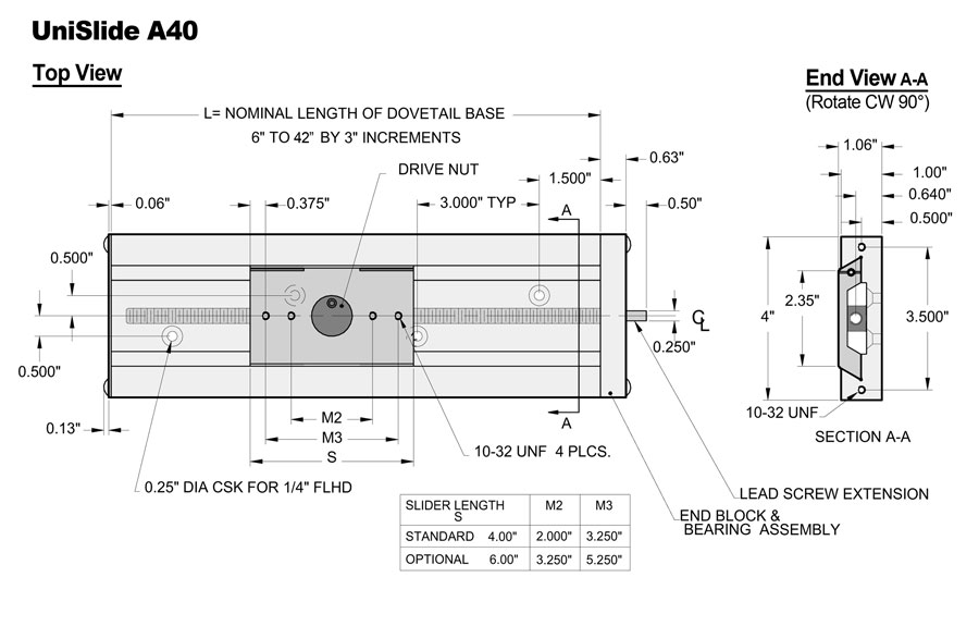
UniSlide A40 Series – Body width 4 inches, slider length of 4 inches carrying a 100 lbs. horizontal load. |
 |
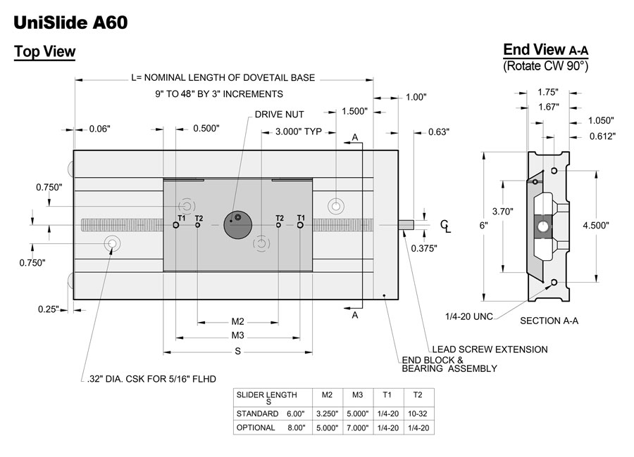
UniSlide A60 Series – Body width 6 inches, slider length of 6 inches carrying a 240 lbs. horizontal load. |
 |
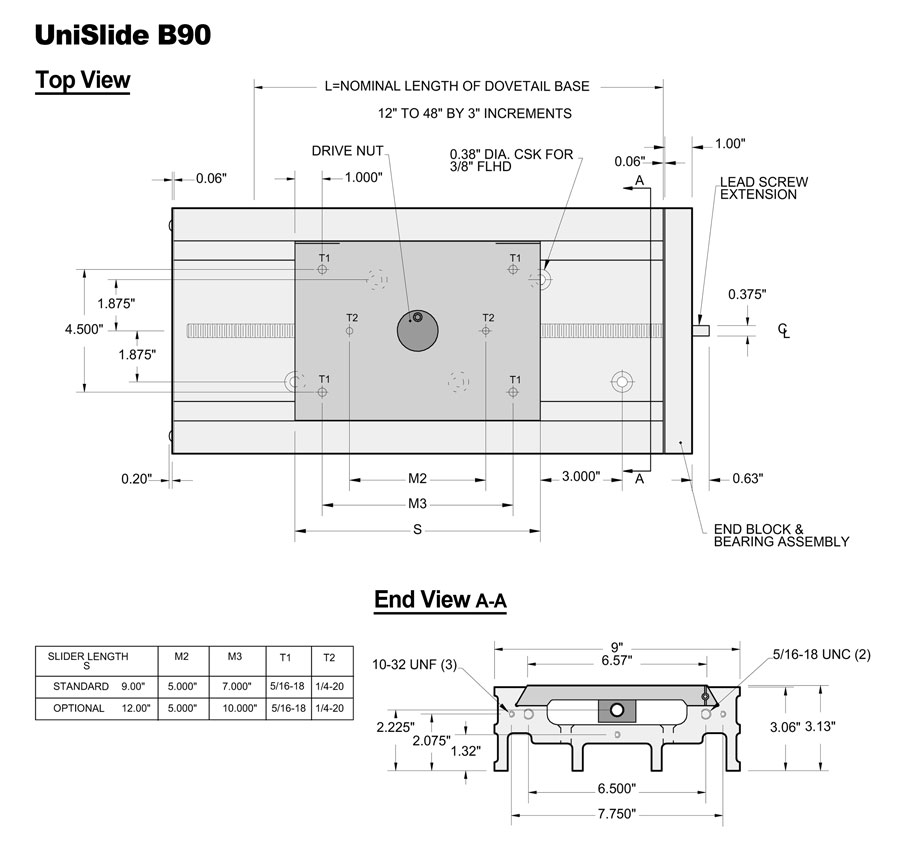
UniSlide B90 Series – Body width 9 inches, slider length of 9 inches carrying a 400 lbs. horizontal load. PLEASE NOTE: The UniSlide® B9000 Series will be discontinued. Please call for availability. Consider using a Velmex BiSlide® as an alternative. Contact Velmex engineering to substitute the BiSlide.| |
Linear UniSlide Assembly Style Options
The UniSlide Series above and the styles below combine to create a complete UniSlide Assembly. Additional options and accessories can be added (See Options/Accessories). Standard style options for UniSlide Assemblies include:
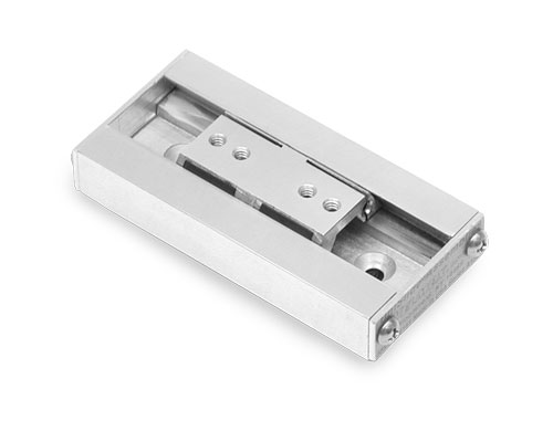 |
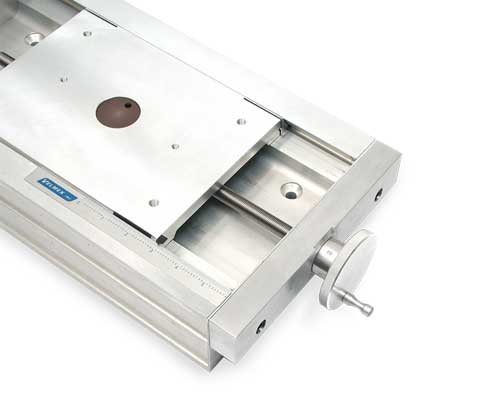
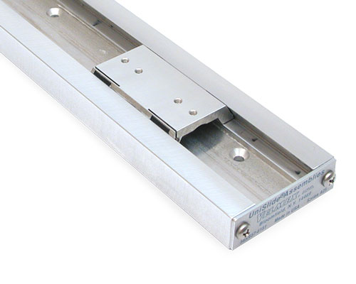
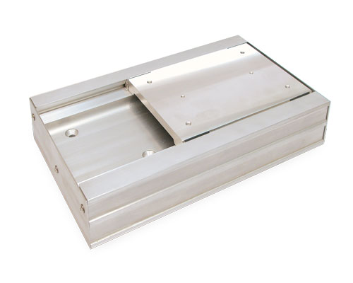
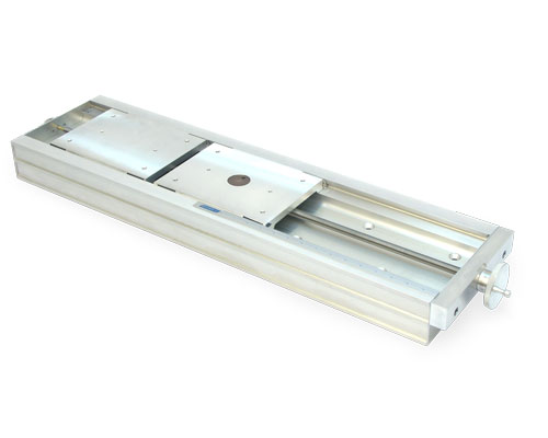
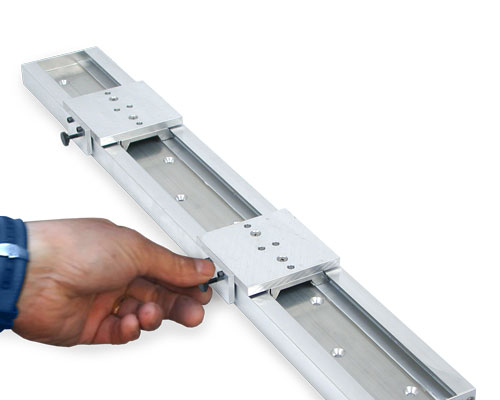
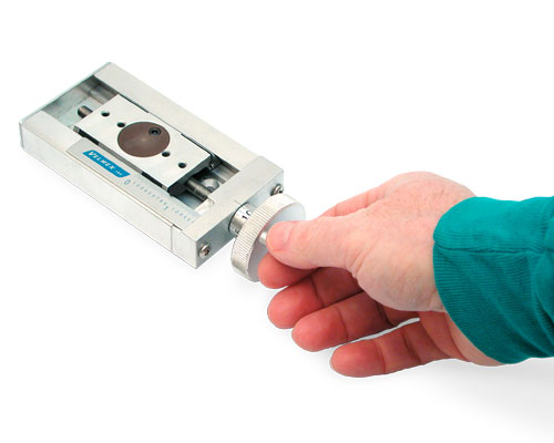
Free Sliding Models – The simplest UniSlide Assembly where the slider is moved by hand. This features a linear dovetail bearing for smooth motion. Configuration available on A15, A25, A40, A60 and B90 Series. |
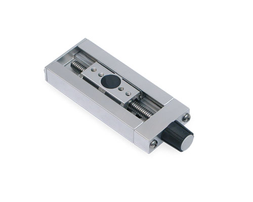 |
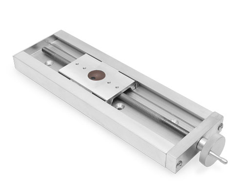
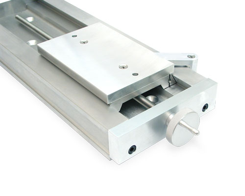
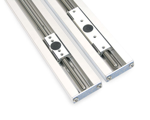
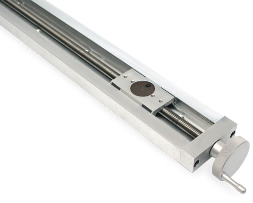
Screw Drive Models – Slide movement is controlled by a lead screw. Velmex lead screws are formed by rolling through precision dies rather than cut on a screw machine, delivering higher quality and accuracy. There are a variety of different diameter lead screws available from 1/4" to 1/2" and 7 mm to 14 mm. Each have different advance ratings. Configuration available on A15, A25, A40, A60 and B90 Series. |
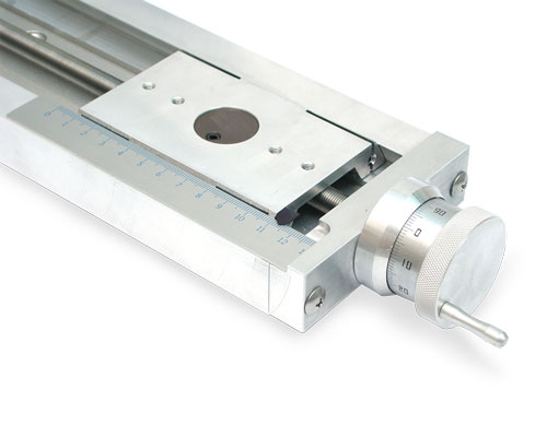 |
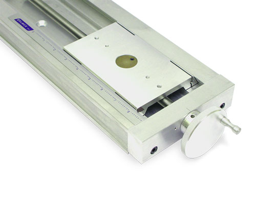
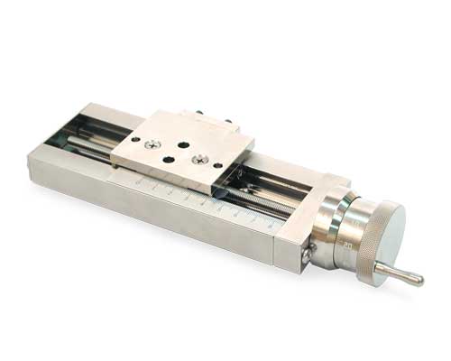
Graduated Knob Models – The position of the payload is measured by combining the readings from the linear scale and engraved knob or drum dial. Measures position from 0.001" or 0.01 mm. Configuration available on A15, A25, A40, A60 and B90 Series. |
 |
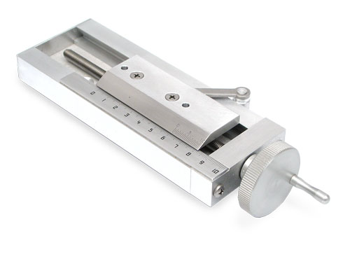
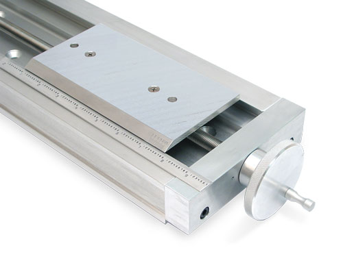
Scale and Vernier Screw Drive Models – Slide movement is controlled by a lead screw. Velmex lead screws are formed by rolling through precision dies rather than cut on a screw machine, delivering higher quality and accuracy. There are a variety of different diameter lead screws available from 1/4" to 1/2" and 7 mm to 14 mm. Each have different advance ratings. Configuration available on A15, A25, A40 and A60 Series. |
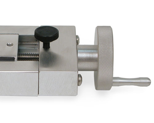
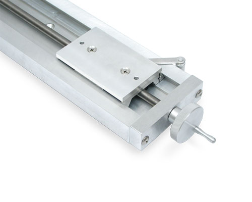
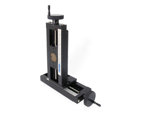
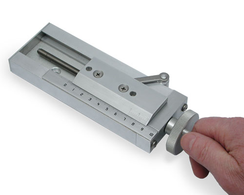
Rapid Advance Models – Are for quickly repositioning the slider by uncoupling the drive system. This saves time when the slider will be moved frequently or when the base length is long. Each have varying lengths of fine adjustment. The limited fine adjust models use a clamping-like drive. The unlimited fine adjust models use a lead screw and pinion design. Rapid Advance models are not recommended for vertical (Z axis) mounting. |
|
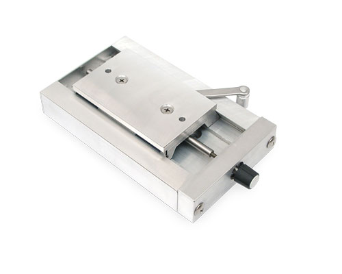 |
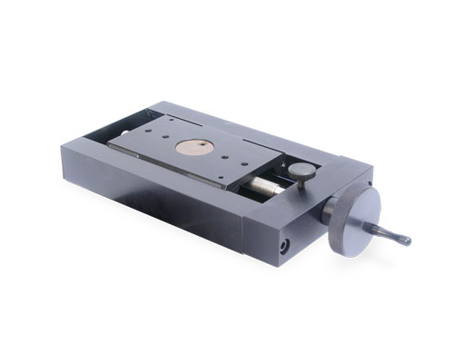
Rapid Advance with Limited Fine Adjust – Have 1/2" of fine pitch adjustment control. Configuration available on A15, A25 and A40 Series. |
 |
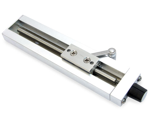
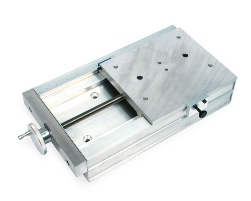
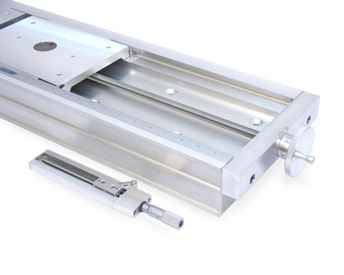
Rapid Advance with Unlimited Fine Adjust – Can be finely adjusted along the full length of the travel. Load is limited to 50 pounds horizontal or 2 pounds vertical. Configuration available on A25, A40 and A60 Series. |
 |
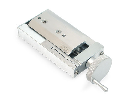
Rapid Advance with Scale and Vernier – Both the limited and unlimited fine adjust are also available with an English or Metric scale and vernier. Configuration available on A15, A25 and A40 Series in the limited adjust. Configuration available on A25, A40 and A60 Series in the unlimited adjust. |
|
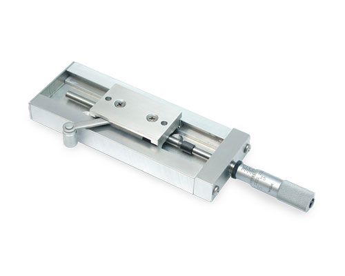
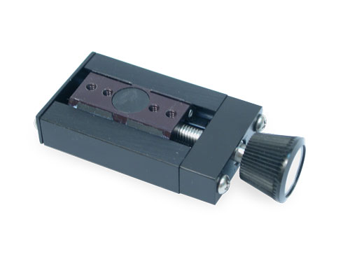
Rapid Advance with Micrometer Head – The limited fine adjustment is made with a micrometer calibrated to 0.001". (0.01 mm metric available as s special order. Contact Velmex.) Configuration available on A15, A25 and A40 Series. |
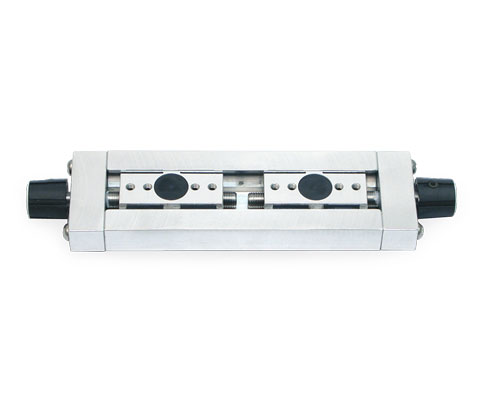
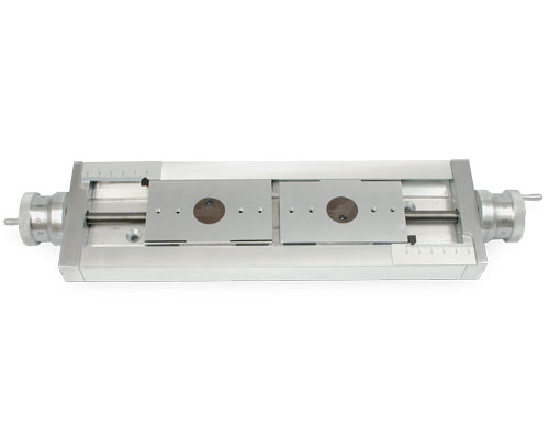
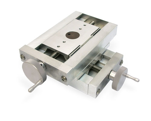
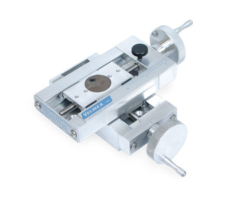
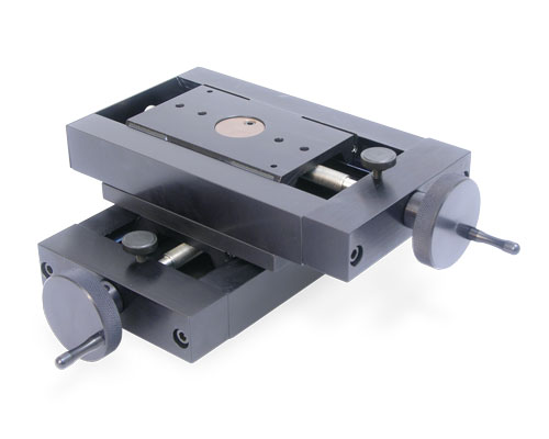
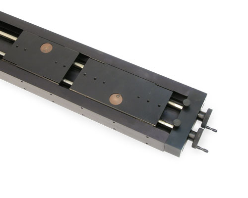
Left-Right Screw / Dual Screw Models – Left-Right models use two carriages (sliders) and have a common lead screw machined with a left thread on one half and a right thread on the other half. A variation of this is the Dual Screw with two independently driven lead screws on the same base with two control knobs for independent motion. Typical uses for these UniSlides include centering or mating operations in manufacturing, testing and research environments. Although not a left-right or dual screw configuration, most UniSlides can accommodate two or more carriages on the same slide. |
|
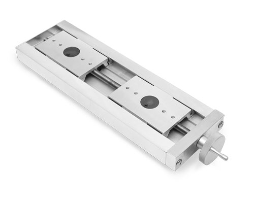 |
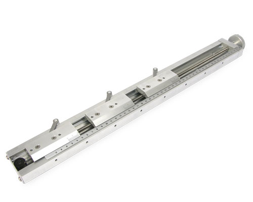
Left-Right Screw Models (LR) – The slides simultaneously move toward or away from each other. Use for applications where two objects must share a common axis of movement. Configuration available on A15, A25 and A40 Series. |
 |
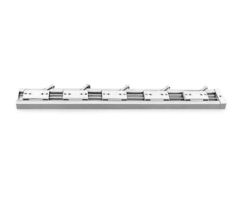
Dual Screw Models (DS) – The slides provide for independent right hand movement from both ends. Configuration available on all UniSlide Series. |
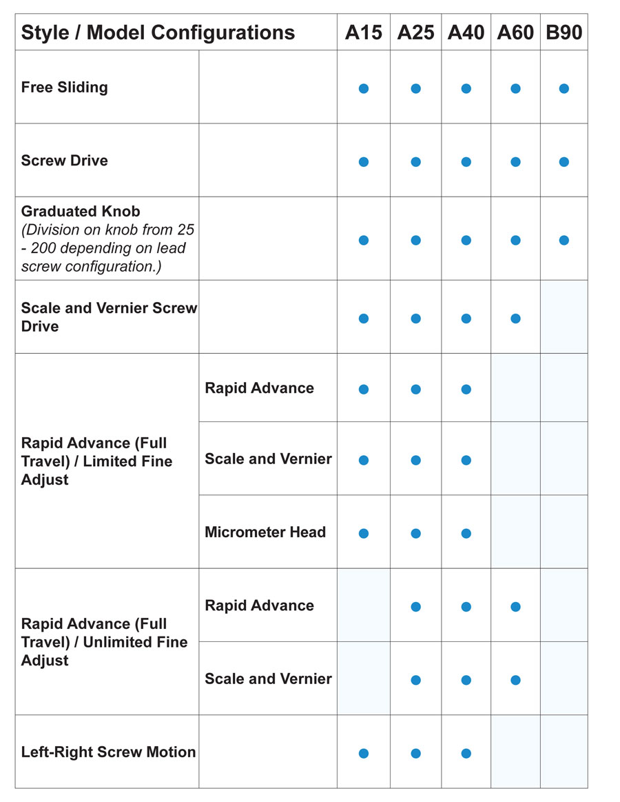
UnSlide Style Configurations
Velmex also offers motorized linear UniSlide Assemblies.
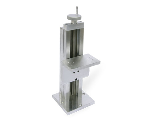
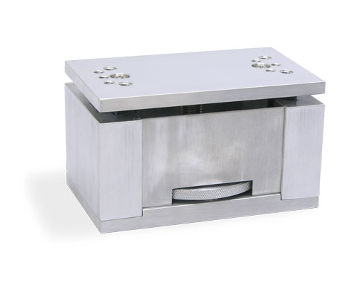
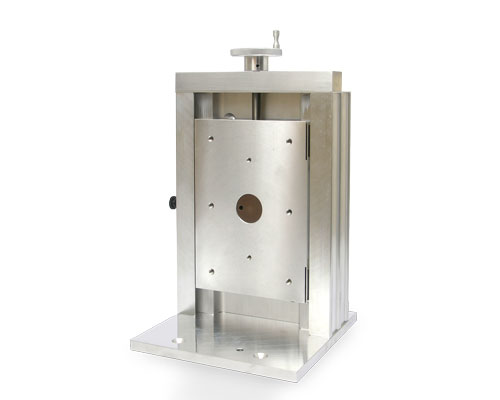
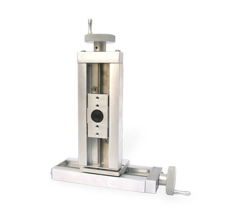
Elevating Tables
| UniSlide Elevating Tables – Designed specifically for vertical lifting with greater strength and rigidity. Please visit the Velmex UniSlide Elevating Tables page for more details. | |
 |
UniSlide B29 Series Elevating Tables – A platform length of 4 inches carrying a 30 lb. load. |
 |
UniSlide B49 Series Elevating Tables – A platform length of 6.5 inches carrying a 100 lb. load. |
 |
UniSlide B69 Series Elevating Tables – A platform length of 6.5 inches carrying a 100 lb. load. |
 |
UniSlide A39 Series Vertical Lift Tables – A platform length of 4 inches carrying a 25 lb. load. |
XY Tables
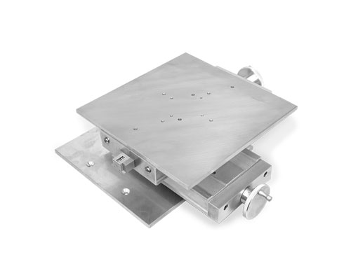
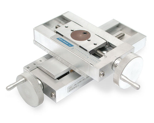
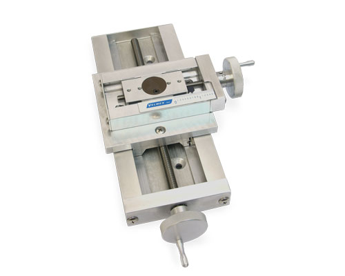
UniSlide XY Tables – Pre-Assembled XY tables save time; each with large work surfaces and stable bases utilizing the A25, A40 and A60 Series of linear slides. Please visit the Velmex UniSlide XY Tables page for more details. Combining linear UniSlides in XY configurations and adding adapter plates can make additional variations of XY tables. |
|
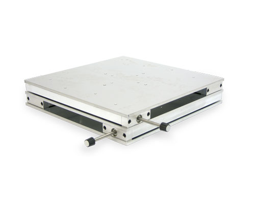 |
UniSlide AXY25 Series Assembled XY Tables – Three low profile (2 5/16") tables with a 25 lb. load. Utilizes four linear A25 UniSlides working in tandem. Solid platform or open aperture. |
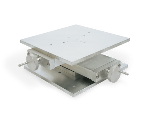 |
UniSlide AXY40 Series Assembled XY Tables – Table height to 3 3/4 inches carrying up to a 100 lb. load. Two models. |
 |
UniSlide AXY60 Series Assembled XY Tables – Table height to 5.5 inches carrying up to a 60 lb. load. Three higher profile models. |
Velmex also offers motorized UniSlide XY Table Assemblies.
UniSlide Special Applications/Configurations
| Velmex has pre-assembled several UniSlide Systems for specific applications. These include: | |
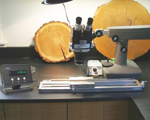 |
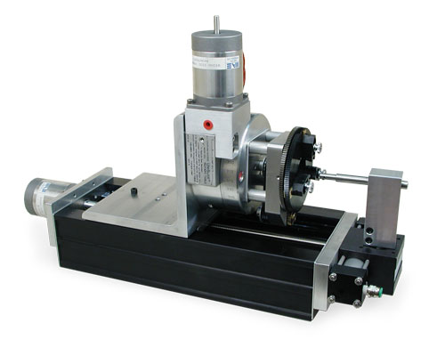
UniSlide TA Measuring Systems – Used for non-contact measurement analysis including tree ring measurement. For more details on the TA Measuring System, please visit the Velmex Tree Ring Measuring page. |
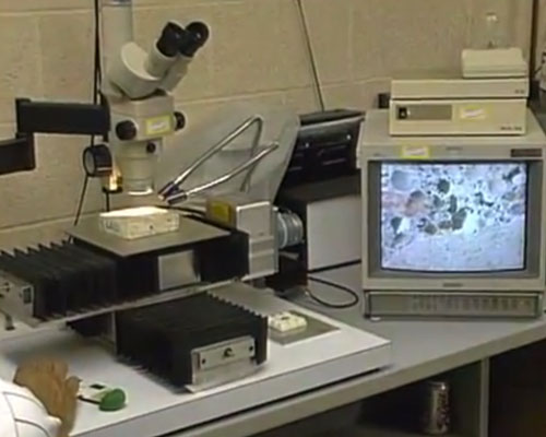 |
Petrographic Analysis Positioning Systems – Used for measuring air entrainment in concrete. Can be a UniSlide or BiSlide® System. For more details on Velmex systems for Petrographic Analysis, please visit the Velmex Petrographic System page. |
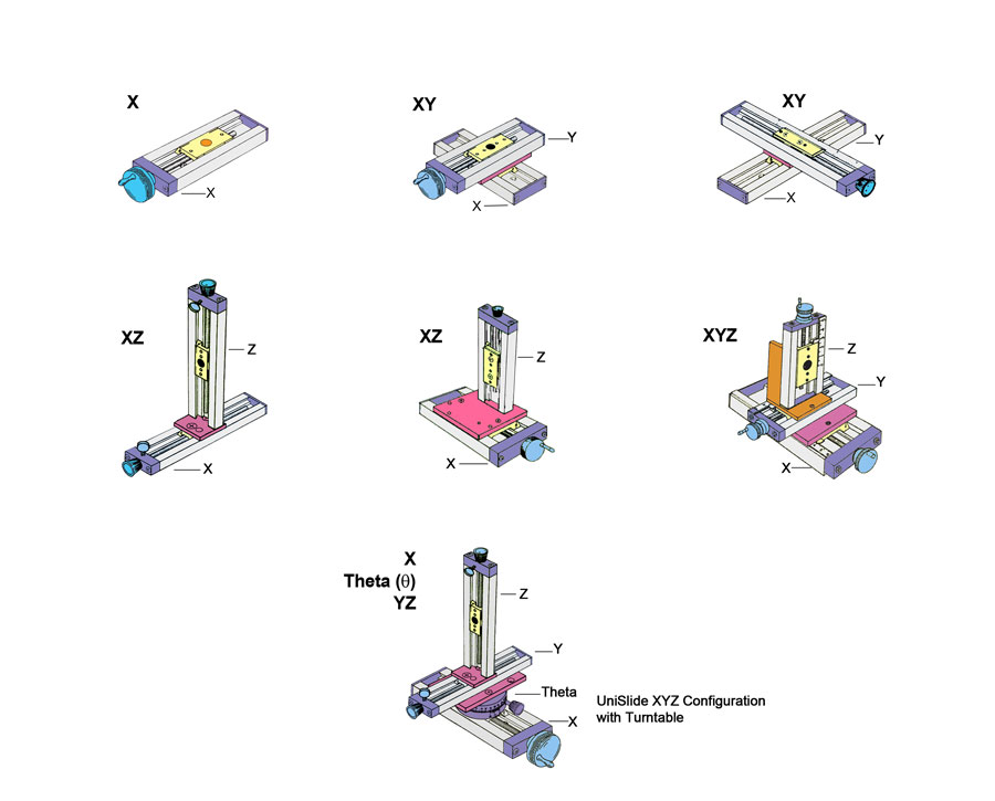
UniSlide Configurations
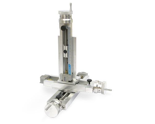
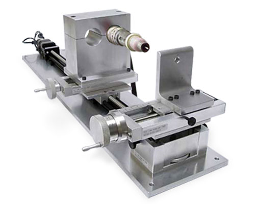
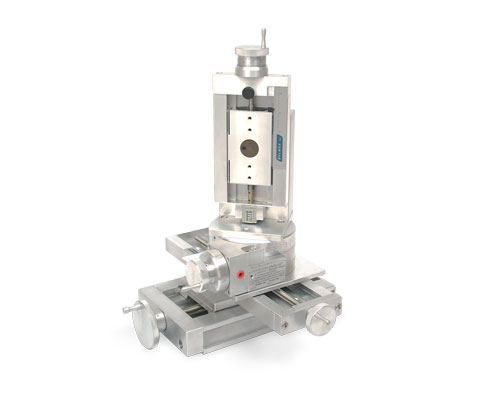
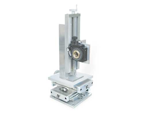
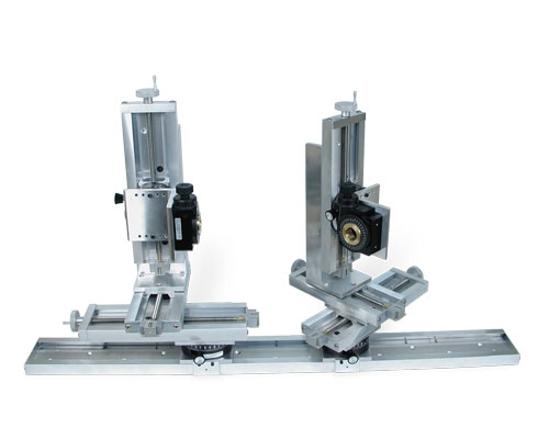
The basic linear UniSlide is a 1-axis stage. One axis UniSlides can be combined for multiple axes in a wide range of lengths and payload capacities. See Examples for images of various multi-axis UniSlides and combinations that include other Velmex stages.
UniSlide® Specifications – Manually-Operated Assemblies
Factors such as size of the motor, size of the payload, travel distance, mounting direction/plane, etc. effect the actual capability of any assembly. Please contact Velmex Application Engineers to configure a system that will meet your exact requirements. Visit the individual pages for each Series for more specific information.
| UniSlide® | Travel Distance‡ | Base Length | Slider Length | ||||
| Series | Inches | cm | Inches | cm | Inches | cm | |
| A15 | |
1.5" - 25.5" | 3.81 – 64.77 | 3" - 27" | 7.62 – 68.58 | 1.5" | 3.81 |
| A25 | |
1.5" - 24.5" | 3.81 – 62.23 | 3" - 27" | 7.62 – 68.58 | 2.5" | 6.35 |
| A40 | |
2" - 38" | 5.08 – 96.52 | 6" - 42" | 15.24 – 106.68 | 4" | 10.16 |
| A60 | |
3" - 42" | 7.62 – 106.68 | 9" - 48" | 22.86 – 121.92 | 6" | 15.24 |
Call for Availability for B90 Series |
|||||||
| B90 | |
3" - 39" | 7.62 – 99 | 12" - 48" | 30.48 – 121.92 | 9" | 22.86 |
‡Standard travel distances available are in 3" increments.
| UniSlide® | Maximum Horizontal Load (Static) | Weight | Height** | Width | |||||
| Series | lbs. | kg. | lbs. | kg. | Inches | cm | Inches | cm | |
| A15 | |
15 | 6.8 | 0.31 – 1.82 | 0.14 – 0.83 | 0.56" | 1.42 | 1.5" | 3.81 |
| A25 | |
30 | 13.6 | 1 – 3.68 | 0.45 – 1.67 | 0.81" | 2.06 | 2.5" | 6.35 |
| A40 | |
100 | 45.5 | 2.4 – 11 | 1.1 – 5 | 1.06" | 2.69 | 4" | 10.16 |
| A60 | |
240 | 109 | 8 – 40.5 | 3.6 – 18.37 | 1.75" | 4.45 | 6" | 15.24 |
Call for Availability for B90 Series |
|||||||||
| B90 | |
400 | 182 | 21 –59.75 | 9.5 – 27.10 | 3.13" | 7.95 | 9" | 22.86 |
** Deeper base "B" configurations available.
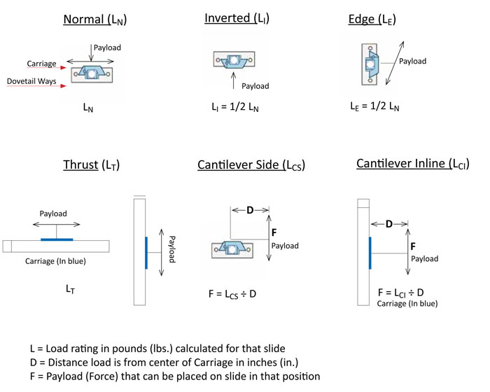
Loads for Manual UniSlides
| UniSlide® | Maximum Horizontal Load (Static) | Cantilevered Load (Static) | Vertical Central (Static) | ||||
| Maximum (Static) Load Capacity | lbs. | kg. | lbs.-in | N-m | lbs. | kg. | |
| A15 | |
15 | 6.8 | 20 lb-in | 2.26 N-m | 10 | 4.5 |
| A25 | |
30 | 13.6 | 40 lb-in | 4.52 N-m | 10 * | 4.5 * |
| A40 | |
100 | 45.5 | 130 lb-in | 14.7 N-m | 50 | 22.7 |
| A60 | |
240 | 109 | 320 lb-in | 36.2 N-m | 100 | 45 |
Call for Availability for B90 Series |
|||||||
| B90 | |
400 | 182 | 480 lb-in | 54.2 N-m | 100 | 45 |
* For A25 models with 1/4" or 7 mm diameter lead screws: 10 lb or 4.5 kg
* For A25 models with 3/8" or 10 mm diameter lead screws: 30 lb or 15.5 kg
| UniSlide® | Load Normal (LN)* | Load Thrust (LT)* | Cantilever Side (LCS)* | Cantilever Inline (LCI)* | |||||
| Normal (Operating) Load Capacity | lbs. | kg. | lbs. | kg. | lbs.-in | N-m | lbs.-in | N-m | |
| A15 | |
5 | 2.27 | 1 | 0.45 | 5 lb-in | .6 N-m | 10 lb-in | 1.13 N-m |
| A25 | |
10 | 4.54 | 3 | 1.36 | 10 lb-in | 1.13 N-m | 20 lb-in | 2.26 N-m |
| A40 | |
40 | 18.14 | 20† | 9.07† | 32 lb-in | 3.62 N-m | 64 lb-in | 7.23 N-m |
| A60 | |
80 | 36.29 | 40† | 18.14† | 80 lb-in | 9.04 N-m | 160 lb-in | 18.07 N-m |
Call for Availability for B90 Series |
|||||||||
| B90 | |
140 | 63.5 | 70 | 31.75 | 120 lb-in | 13.6 N-m | 240 lb-in | 27.11 N-m |
* Normal Operating Loads are less than the maximum. For the recommended maximum limit see prior chart.
† 5 lbs max for Rapid Advance models.
| Repeatability | 0.00015" (4 microns) typical |
| Straight line accuracy | Bow - 0.002" per foot; Run Out - 0.001" per foot; Twist - 1 milliradian per foot |
| Screw lead accuracy | Standard Lead Screw: 0.007"/10" Precision Lead Screw: 0.0015"/10" or better available. Consult factory. |
| Operating temperature | 0 to 180° F (-18 to 82° C) |
| Properties of Velmex Stages | Information on stage composition, tolerances, wear and design for specialty applications. |
| Load Parameters | Definitions and parameters that effect the various load ratings. |
Lead Screws
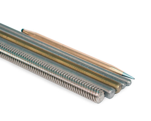 A wide selection of high-quality lead screws provide flexibility in designing the drive portion of Velmex translation stages.
The lead screws we use are all manufactured by us to exacting standards. They are formed by rolling through precision dies rather than cutting on a screw machine, resulting in higher quality and accuracy. The screws are made of either 303 stainless steel or electroless nickel-plated, cold rolled steel. Other materials are available for specialized applications. Please check with our Application Engineers for details.
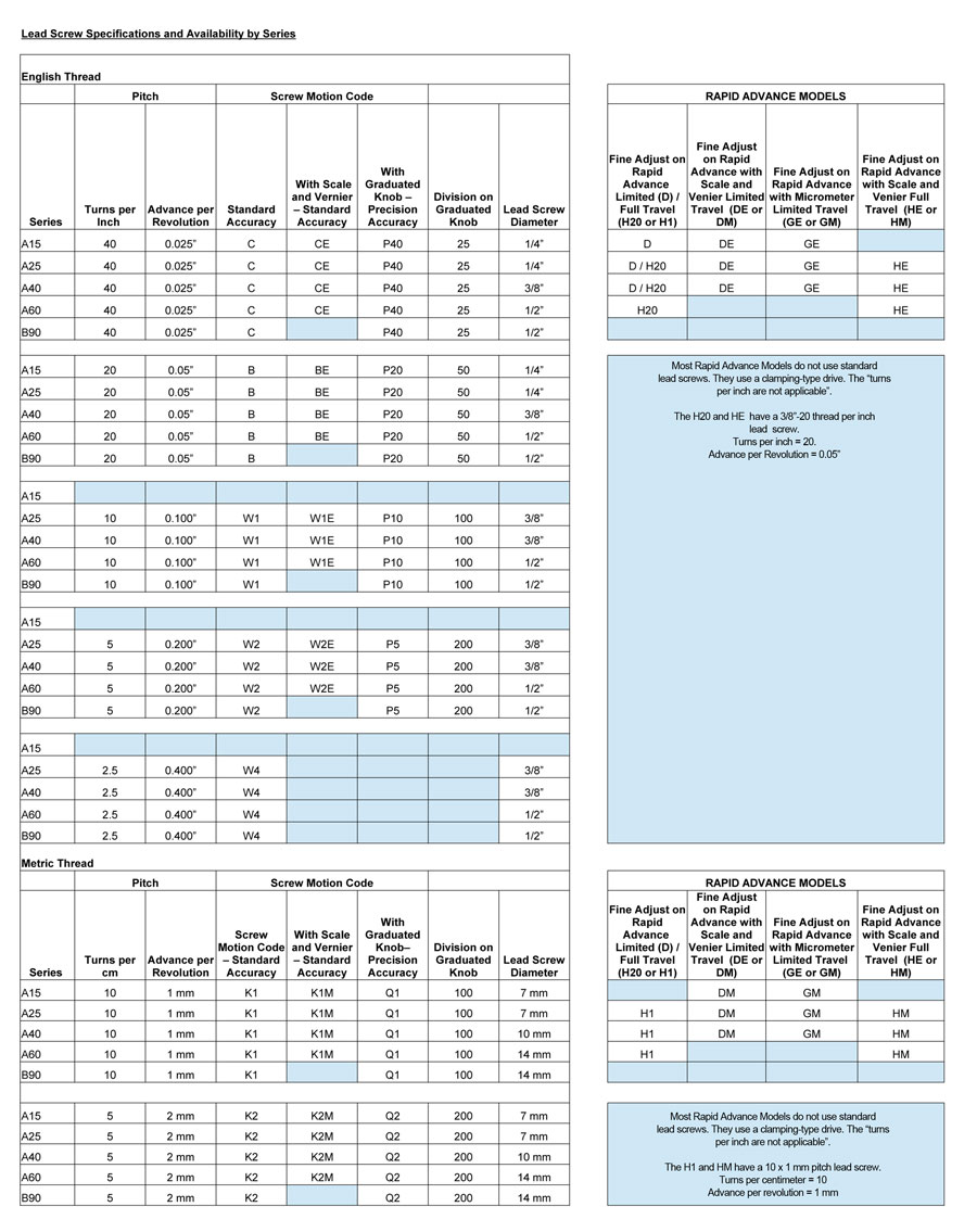
The lead screws are available in a range of diameters with both English and Metric Threads. The pitch for English Thread lead screws range from 2.5 turns per inch to 40 turns per inch. The Metric lead screws range from 5 turns to 10 turns per metric thread. We offer both Standard accuracy and Precision accuracy (Precision grade) screws.
In addition we make specialized left and right hand threaded lead screws for together and apart movement of the payload carriage on linear stages.
The following chart shows the lead screw specifications for manual UniSlide Stages.
Visit the Velmex Elevating Table Page for specifications for Elevating Tables Series A39, B29, B49 and B69.
Visit the Velmex XY Table Page for specifications for XY Tables Series AXY25, AXY40 and AXY60.
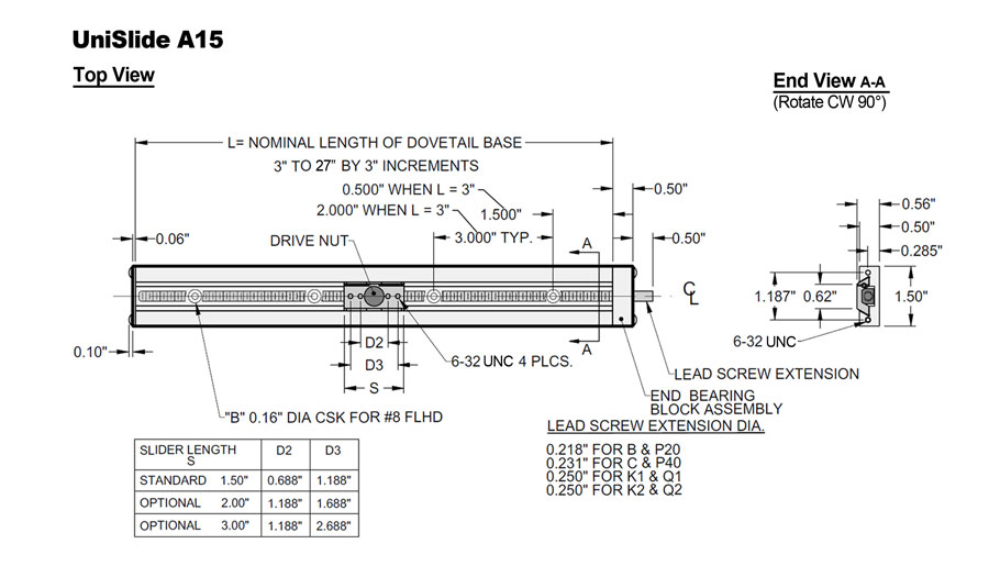
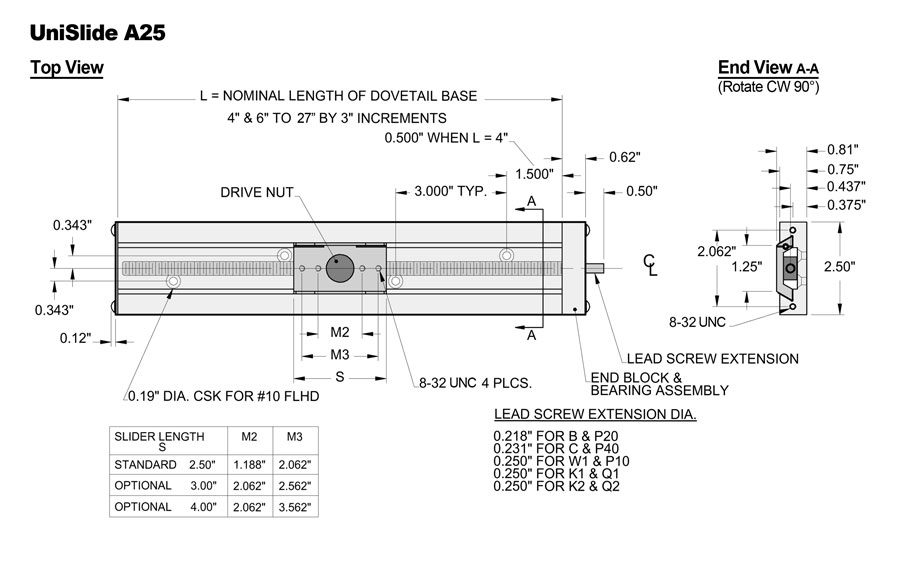
Click on the tab to view the dimensional drawings for the various Series of UniSlide Linear stages.
- A15 Series Dimensions
- A25 Series Dimensions
- A40 Series Dimensions
- A60 Series Dimensions
- B90 Series Dimensions
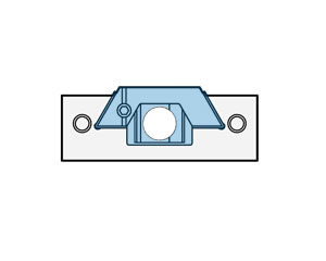
UniSlide Base Cross-Section
The slider / carriage (shaded area in the cross-section to the left.) rides on the inside of the dovetail ways.
UniSlide Load Calculations
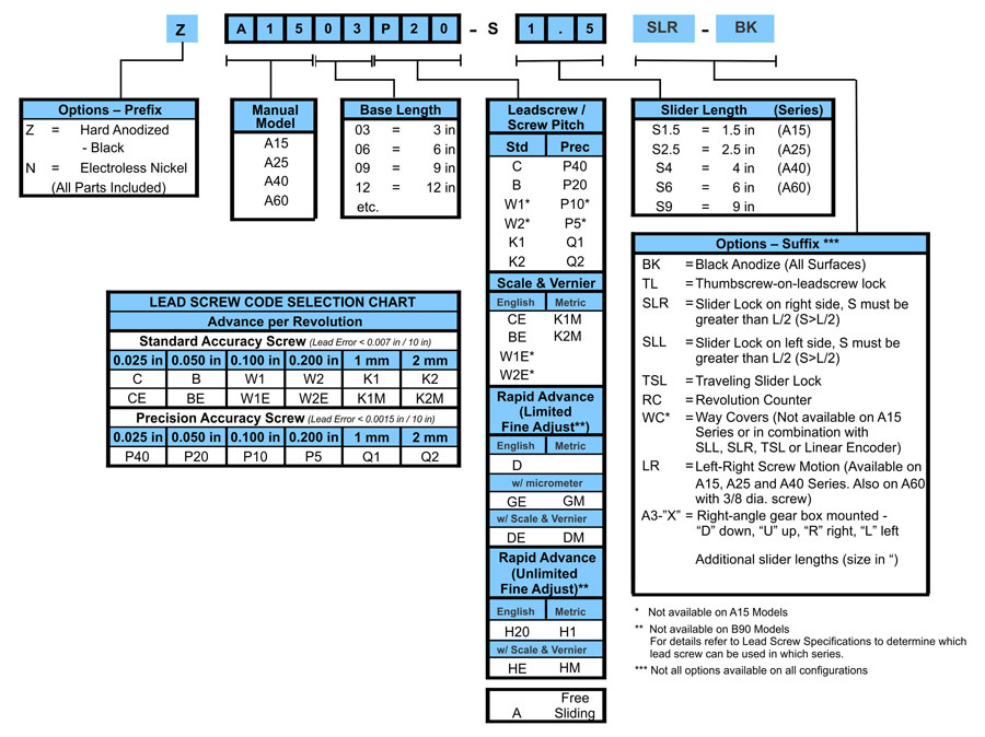
UniSlide Manual Part Numbers
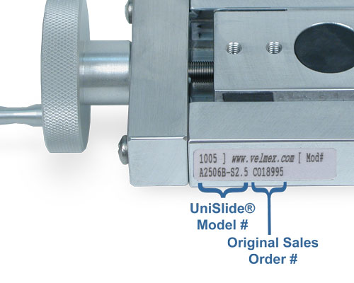
All manual linear UniSlide Assemblies have the same basic part number configuration. The number varies with the series, the travel distance, the lead screw and the slider length. Additional prefixes and suffixes are added for the options and accessories. You can determine the UniSlide part number using the chart below. The number can be found on the side or end of any Velmex device you may already own.
 |
The part number can be found on the side of the UniSlide Assembly. |
 |
|---|
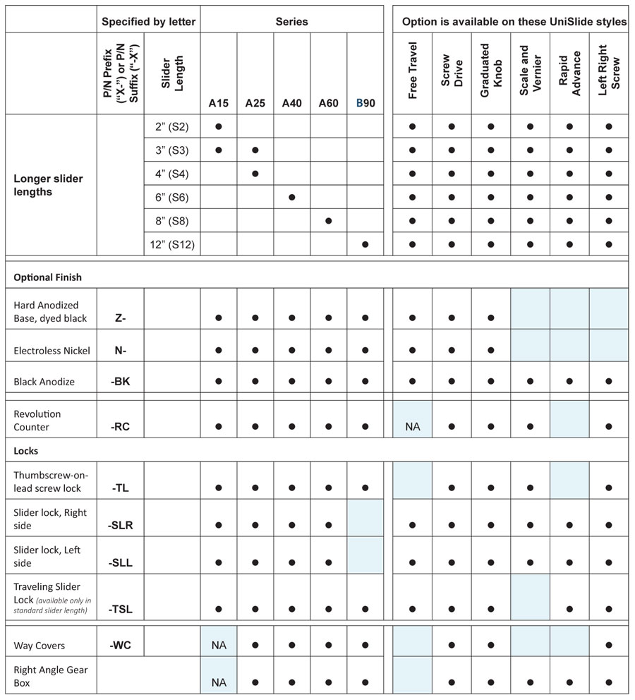
Options/Accessories for Manual Velmex UniSlides®
The versatility of Velmex UniSlide Assemblies for a multitude of applications comes from the array of options and accessories available. Not all options and accesories can be used on every model and style of UniSlide. Please check the Option Chart for what each UniSlide model can accommodate.
Adapter Plates |
|||||||||||||||||
|
XY Plates – allow two UniSlides to be converted into an XY motion system. The aluminum plates mate the slider of the lower (X) UniSlide at a right angle to the base of the top (Y) UniSlide. You can combine UniSlides of the same series, same lengths, different series and varying lengths for a virtually limitless selection of configurations. You can also can also combine motorized and manual UniSlides. The plates can also be used as auxiliary payload mounting plates. This provides more mounting surface area for the payload, although it does not increase the size of the load the UniSlide can handle. The Adapter Plates also provide an easy way to mount a UniSlide upside (slider) down. For more specifics and to see the adapter plates in use on a Velmex stage visit the UniSlide Adapters page. |
|||||||||||||||||
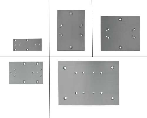 |
A1500XY Adapter Plate – To mount an A15 Series UniSlide to another A15 Series in XY. |
||||||||||||||||
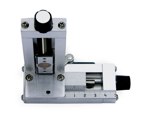
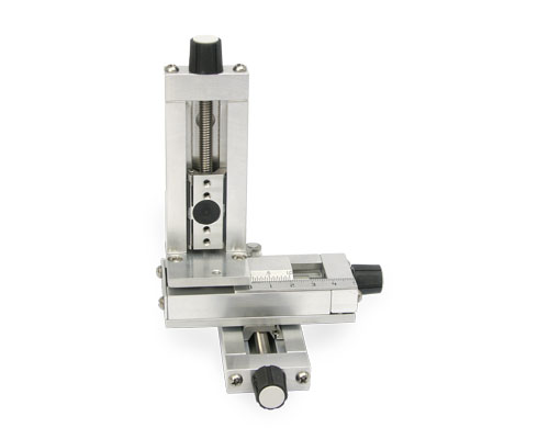
XZ Plates – Allow UniSlide assemblies to be positioned vertically facing in any of four directions. The adapter plates allow the vertical stage to be end mounted to the carriage on the horizontal base stage. The plates connect to the given series and the next smaller size. The XZ Plates are for light loads and short slides. For more specifics and to see the adapter plates in use on a Velmex stage visit the UniSlide Adapters page. |
|||||||||||||||||
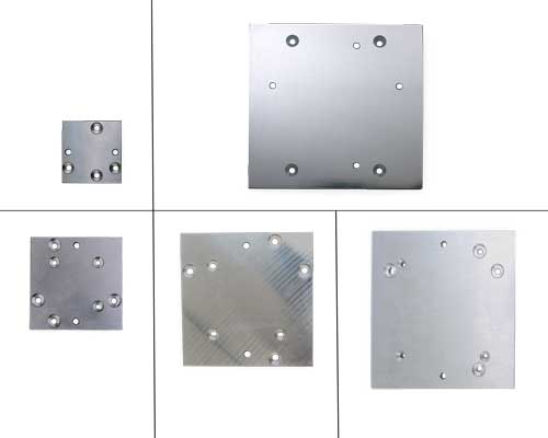 |
A1500XZ Adapter Plate– To mount an A15 Series UniSlide to another A15 Series in XZ. |
||||||||||||||||
XZ Brackets – allow UniSlide assemblies to be positioned vertically, facing in any of four directions and perpendicular to the X or Y plane. The brackets support the base of the vertical unit to provide more rigidity and handle heavier loads. For more specifics and to see the brackets in use on a Velmex stage visit the UniSlide Adapters page. |
|||||||||||||||||
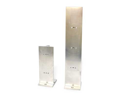 |
A2501XZ Adapter Bracket – To mount an A25 Series UniSlide to another A25 Series (6"- 9") or to an A15 Series (6"- 9") in XZ. (The A25 would be the base horizontal stage. The other stage would be mounted vertically.) |
||||||||||||||||
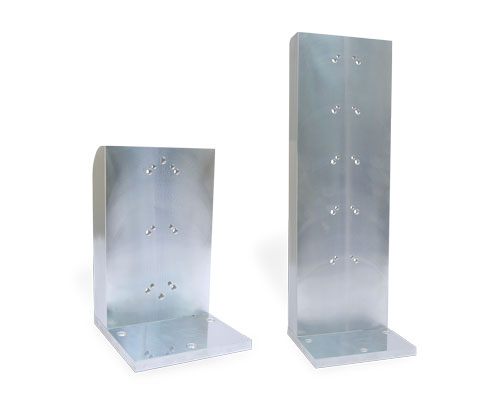 |
A6001XZ Adapter Bracket– To mount an A60 Series UniSlide to another A60 Series (up to 12") or to an A40 Series (up to 12") in XZ. (The A60 would be the base horizontal stage.) |
||||||||||||||||
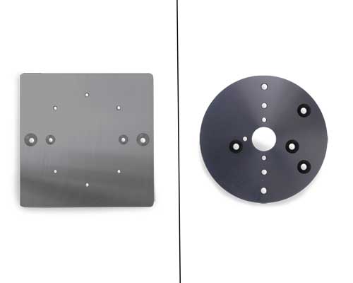 |
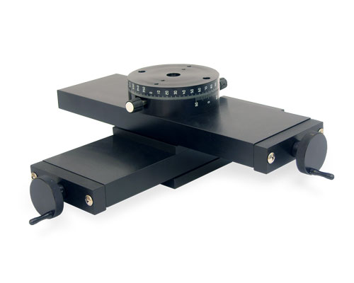
Rotary Table Adapter Plates –To mount Velmex Rotary Tables to UniSlide Assemblies either in horizontal or vertical positions. |
||||||||||||||||
A6000TX Adapter Plate – To mount an A48 Series Rotary Table to an A40 Series or A60 Series UniSlide. (The UniSlide would be the base horizontal stage.) |
|||||||||||||||||
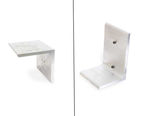 |
Platform Shelf – A right angled bracket designed to be used with UniSlide® Elevating Tables. However, they also can be used with vertically mounted UniSlide Assemblies to support a payload. The shelf can be inverted depending on the motion required. For more specifics and to see the shelf in use on a Velmex stage visit the UniSlide Adapters page. |
||||||||||||||||
 |
Slider Lengths – Varying length carriages (sliders) can be added to all models of UniSlide Assemblies. See chart for acceptable sliders for each series. Choosing a longer length slider reduces the standard travel distance.
|
||||||||||||||||
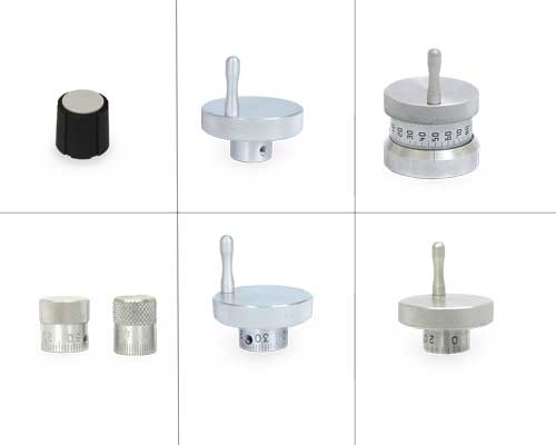 |
Alternative Knobs – A variety of knob styles can be substitute for the standard knob available on the particular style/model of UniSlide Assembly. See UniSlide Knob Specification for which knob is available on which series and configuration. |
||||||||||||||||
• Small diameter (5/8") Rogan knob for some A15, A25, A40 Models and Turntables |
|||||||||||||||||
Locks – There are a number ways to lock the carriage (slider) position on UniSlides. They include: |
|||||||||||||||||
 |
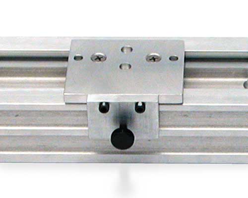
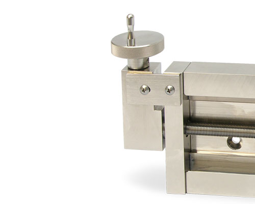
Thumbscrew-on-Lead-Screw Lock (-TL) – An easy method to fix the slider utilizing a simple thumbscrew. The thumbscrew lock increases the overall length of the UniSlide base. This lock type is not available on Rapid Advance models. |
||||||||||||||||
 |
Traveling Slider Lock (-TSL) – This lock attaches to the slider to lock the carriage in place. Available on Free Sliding, Screw Motion and Graduated Knob models only. |
||||||||||||||||
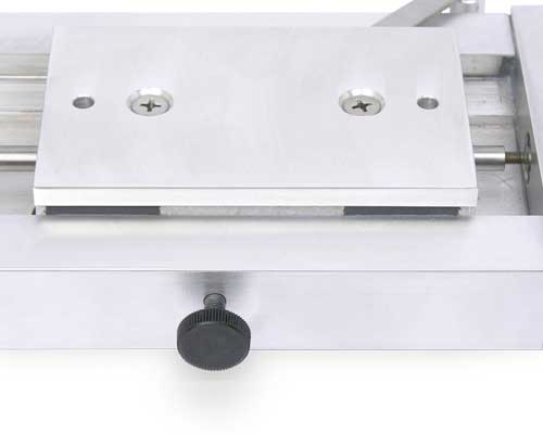 |
Slider Lock (-SLR or -SLL) – This lock is mounted at the mid-point on the base and is tightened to prevent slider movement. This is only available on slides where the carriage (slide) length is greater than one-half the base length. It can be mounted on the right (-SLR) or left (-SLL) of the base. |
||||||||||||||||
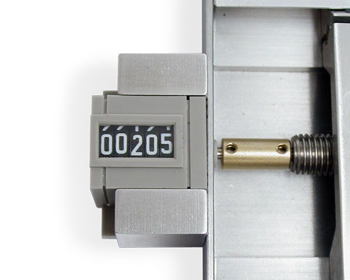 |
Revolution Counter (-RC) – A mechanical revolution counter provides a convenient 1/10 revolution increment count. Readouts in either 0.01" or 0.1 mm. Counts precisely with 0.100" or 1 mm lead screws. Other screws require additional calculations. For details see UniSlide Counter page. |
||||||||||||||||
|
Left-Right Screw Motion – This configuration is very useful for applications where two objects must share a common axis of movement. This assembly incorporates two carriages driven by a single right- and left-hand threaded lead screw. When the knob is turned, the carriages simultaneously move toward or away from each other. |
||||||||||||||||
|
Two Independent Carriages – a variation on the left-right screw motion UniSlide is one containing two lead screws with control knobs at both ends of the assembly. Each lead screw and carriage operates independently. |
||||||||||||||||
 |
Right Angle Gearbox – Allows the control knob or wheel to be offset perpendicular to the UniSlide ways. Ideal for tight spaces or applications where access to the end of the stage is limited. Available on A25, A40, A60 and B90 Series. For more specifics and to see the gearbox in use on a Velmex stage visit the UniSlide Adapters page. |
||||||||||||||||
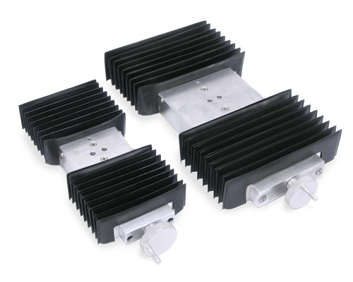 |
Way Covers (-WC) – Protect the slider and dovetail base from dust, dirt and grit that could hamper the efficient operation of the slide. Way covers increase slider height and reduce the travel length of linear UniSlide stages. Not available on Series A15 Assemblies. Available on free sliding, screw drive and graduated knob models of the other assemblies. For more details visit the Way Cover page. |
||||||||||||||||
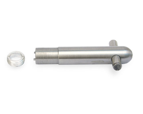 |
Wrench - Retainer Nut – Velmex has a custom-designed wrench to easily adjust and remove the threaded retainer nut on UniSlides. When needed, this makes removing and changing the lead screw simple and easy. The wrench is designed for the smaller diameter lead screws (1/4" or 7 mm - A15 Series and some A25) with the split Delrin® thrust bearings and the threaded retainer nut. Note: larger diameter lead screws (3/8", 1/2", 10 mm and 14 mm) use steel bearings and a snap ring retainer. |
||||||||||||||||
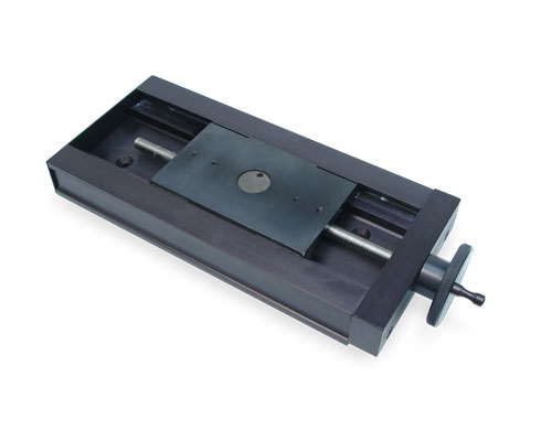 |
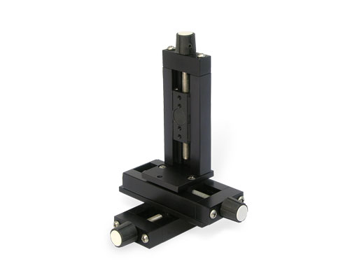
Finishes – Standard UniSlide Assemblies have a brushed aluminum finish. Optional finishes are available at an additional charge and include: |
||||||||||||||||
• Black Anodizing, additional colors also available. (pictured) |
|||||||||||||||||
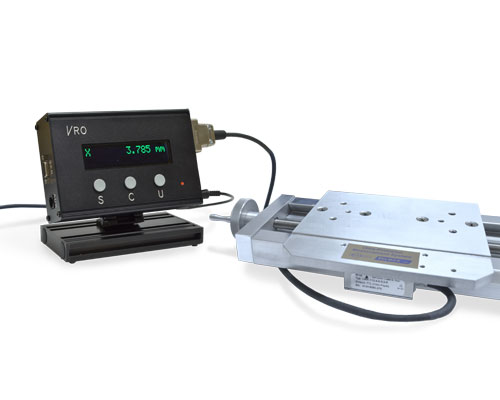 |
Encoders and VRO™ Encoder Readout – For a high resolution position readout an encoder and Velmex's VRO encoder readout can be mounted to most linear UniSlide assemblies. An encoder, mounted directly to the slider gives a true and accurate reading eliminating lead screw and backlash errors. The VRO Readout is compatible with all 5V incremental encoders. It can monitor one or two axis. Fully functional, it features automatic memory back-up of settings, sleep mode and self diagnostics. It's highly visible, wide-screen LED display makes it easy to view the positioning results. (Not available on all UniSlide models.) SEE: Velmex Controls on the Encoders and the VRO Readout for additional details. |
||||||||||||||||
Velmex offers a multitude of options and accessories for all its products. Usually an option or an accessory will address your requirements. When it doesn't, we can make custom modifications, including:
• Additional holes or slots. (A drawing is required.)
• Intermediate plates to mount your payload
• Special or in between lengths of the dovetail base
• Lead screw shaft extensions
• Choice of drive nut materials, including brass and Vespel
• Right and left-hand threads on the same lead screw, allowing a pair of sliders to move together or apart.
• Deeper base "B" configurations available.
CAD Drawings / Documents / Instructions
The majority of CAD drawings found in our Technical Library are Step (.stp) files. You will also see .dxf, .dwg, .sat and .pdf files. For .STP files, you may need to right click on the download button and save the "target" or "link". If you require a different format or cannot located the drawing you require, please contact us. Drawings are identified by the series and configuration. The complete part number can be found on the side or end of any Velmex device you may already own.
NOTE: Lead Screw pitch variations are represented by a single drawing number. For example - A2506P10-S2.5 becomes A2506XXX-S2.5
For non-standard sizes or multi-axis configurations, please contact us. There may be an additional charge.
| Click to open the section you need: | "Right Click" to download. |
Free Slides
| Series | Type | File Name | Description | Download | View |
|---|---|---|---|---|---|
| A15 | STP | A1503A-S1.5.stp | Free slide, 1.5 " Travel | - | |
| A15 | STP | A1506A-S1.5.stp | Free slide, 4.5 " Travel | - | |
| A15 | STP | A1509A-S1.5.stp | Free slide, 7.5 " Travel | - | |
| A15 | STP | A1512A-S1.5.stp | Free slide, 10.5 " Travel | - | |
| A15 | STP | A1515A-S1.5.stp | Free slide, 13.5 " Travel | - | |
| A15 | STP | A1518A-S1.5.stp | Free slide, 16.5 " Travel | - | |
| A15 | STP | A1521A-S1.5.stp | Free slide, 19.5 " Travel | - | |
| A15 | STP | A1524A-S1.5.stp | Free slide, 21.5 " Travel | - | |
| A15 | STP | A1527A-S1.5.stp | Free slide, 24.5 " Travel | - |
Lead Screw / Rapid Advance
| Series | Type | File Name | Description | Download | View |
|---|---|---|---|---|---|
| 1.5" Travel | |||||
| A15 | STP | A1503D-S1.5.stp | Rapid Advance, 1.5" Travel | - | |
| A15 | STP | A1503Dx-S1.5_scale_vernier.stp | Rapid Advance with scale and vernier, Lead screw, 1.5" Travel | - | |
| A15 | STP | A1503Gx-S1.5_micrometer.stp | Rapid Advance with micrometer, Lead screw, 1.5" Travel | - | |
| A15 | STP | A1503sv.stp | Lead screw with scale and vernier, 1.5" Travel | - | |
| A15 | STP | A1503gk.stp | Lead screw, graduated knob, 1.5" Travel | - | |
| A15 | STP | A1503xx-S1.5.stp | Lead screw, basic knob, 1.5" Travel | - | |
| A15 | STP | A1503xx-S1.5-TL.stp | Lead screw, basic knob, 1.5" Travel, thumb lock | - | |
| 4.5" Travel | |||||
| A15 | STP | A1506D-S1.5.stp | Rapid Advance, 4.5" Travel | - | |
| A15 | STP | A1506Dx-S1.5_scale_vernier.stp | Rapid Advance with scale and vernier, Lead screw, 4.5" Travel | - | |
| A15 | STP | A1506Gx-S1.5_micrometer.stp | Rapid Advance with micrometer, Lead screw, 4.5" Travel | - | |
| A15 | STP | A1506sv.stp | Lead Screw with scale and vernier, 4.5" Travel | - | |
| A15 | STP | A1506x-S1.5-LR.stp | Lead screw, left/ right, Carriage separation 3" | - | |
| A15 | STP | A1506gk.stp | Lead Screw, graduated knob, 4.5" Travel | - | |
| A15 | STP | A1506xx-S1.5.stp | Lead screw, basic knob, 4.5" Travel | - | |
| 7.5" Travel | |||||
| A15 | STP | A1509D-S1.5.stp | Rapid Advance, 7.5" Travel | - | |
| A15 | STP | A1509Dx-S1.5_scale_vernier.stp | Rapid Advance with scale and vernier, Lead screw, 7.5" Travel | - | |
| A15 | STP | A1509Gx-S1.5_micrometer.stp | Rapid Advance with micrometer, Lead screw, 7.5" Travel | - | |
| A15 | STP | A1509sv.stp | Lead Screw with scale and vernier, 7.5" Travel | - | |
| A15 | STP | A1509x-S1.5-LR.stp | Lead screw, left/ right, Carriage separation 6" | - | |
| A15 | STP | A1509gk.stp | Lead Screw, graduated knob, 7.5" Travel | - | |
| A15 | STP | A1509xx-S1.5.stp | Lead screw, basic knob, 7.5" Travel | - | |
| 10.5" Travel | |||||
| A15 | STP | A1512D-S1.5.stp | Rapid Advance, 10.5" Travel | - | |
| A15 | STP | A1512Dx-S1.5_scale_vernier.stp | Rapid Advance with scale and vernier, Lead screw, 10.5" Travel | - | |
| A15 | STP | A1512Gx-S1.5_micrometer.stp | Rapid Advance with micrometer, Lead screw, 10.5" Travel | - | |
| A15 | STP | A1512sv.stp | Lead Screw with scale and vernier, 10.5" Travel | - | |
| A15 | STP | A1512x-S1.5-LR.stp | Lead screw, left/ right, left / right model with dual carriages, Carriage separation 9" | - | |
| A15 | STP | A1512gk.stp | Lead Screw, graduated knob, 10.5" Travel | - | |
| A15 | STP | A1512xx-S1.5.stp | Lead screw, basic knob, 10.5" Travel | - | |
| 13.5" Travel | |||||
| A15 | STP | A1515D-S1.5.stp | Rapid Advance, 13.5" Travel | - | |
| A15 | STP | A1515Dx-S1.5_scale_vernier.stp | Rapid Advance with scale and vernier, Lead screw, 13.5" Travel | - | |
| A15 | STP | A1515Gx-S1.5_micrometer.stp | Rapid Advance with micrometer, Lead screw, 13.5" Travel | - | |
| A15 | STP | A1515sv.stp | Lead Screw with scale and vernier, 13.5" Travel | - | |
| A15 | STP | A1515x-S1.5-LR.stp | Lead screw, basic knob, left / right model with dual carriages, Carriage separation 12" | - | |
| A15 | STP | A1515gk.stp | Lead Screw, graduated knob, 13.5" Travel | - | |
| A15 | STP | A1515xx-S1.5.stp | Lead screw, basic knob, 13.5" Travel | - | |
| 16.5" Travel | |||||
| A15 | STP | A1518D-S1.5.stp | Rapid Advance, 16.5" Travel | - | |
| A15 | STP | A1518Dx-S1.5_scale_vernier.stp | Rapid Advance with scale and vernier, Lead screw, 16.5" Travel | - | |
| A15 | STP | A1518Gx-S1.5_micrometer.stp | Rapid Advance with micrometer, Lead screw, 16.5" Travel | - | |
| A15 | STP | A1518sv.stp | Lead screw with scale and vernier, 16.5" Travel | - | |
| A15 | STP | A1518x-S1.5-LR.stp | Lead screw, basic knob, left / right model with dual carriages, Carriage separation 15" | - | |
| A15 | STP | A1518gk.stp | Lead screw, graduated knob, 16.5" Travel | - | |
| A15 | STP | A1518xx-S1.5.stp | Lead screw, basic knob, 16.5" Travel | - | |
| 19.5" Travel | |||||
| A15 | STP | A1521xx-S1.5.stp | Lead screw, basic knob, 19.5" Travel | - | |
| 21.5" Travel | |||||
| A15 | STP | A1524xx-S1.5.stp | Lead screw, basic knob, 21.5" Travel | - | |
| 24.5" Travel | |||||
| A15 | STP | A1527xx-S1.5.stp | Lead screw, basic knob, 24.5" Travel | - | |
Free Slides
| Series | Type | File Name | Description | Download | View |
|---|---|---|---|---|---|
| A25 | STP | A2504A-S2.5.stp | Free Slide, 1.5" Travel | - | |
| A25 | STP | A2506A-S2.5.stp | Free Slide, 3.5" Travel | - | |
| A25 | STP | A2509A-S2.5.stp | Free Slide, 6.5" Travel | - | |
| A25 | STP | A2512A-S2.5.stp | Free Slide, 9.5" Travel | - | |
| A25 | STP | A2515A-S2.5.stp | Free Slide, 12.5" Travel | - | |
| A25 | STP | A2518A-S2.5.stp | Free Slide, 15.5" Travel | - | |
| A25 | STP | A2521A-S2.5.stp | Free Slide, 18.5" Travel | - | |
| A25 | STP | A2524A-S2.5.stp | Free Slide, 21.5" Travel | - | |
| A25 | STP | A2527A-S2.5.stp | Free Slide, 24.5" Travel | - | |
| A25 | STP | A2530A-S2.5.stp | Free Slide, 27.5" Travel | - |
Lead Screw / Rapid Advance
| Series | Type | File Name | Description | Download | View |
|---|---|---|---|---|---|
| 1.5" Travel | |||||
| A25 | STP | A2504D-S2.5.stp | Rapid Advance - limited adj., 1.5" Travel | - | |
| A25 | STP | A2504Dx-S2.5_scale_vernier.stp | Rapid Advance - limited adj. with scale and vernier, 1.5" Travel | - | |
| A25 | STP | A2504Gx-S2.5_micrometer.stp | Rapid Advance - limited adj. with micrometer, 1.5" Travel | - | |
| A25 | STP | A2504Hx-S2.5_scale_vernier.stp | Rapid Advance - unlimited adj. with scale and vernier, 1.5" Travel | - | |
| A25 | STP | A2504Hxx-S2.5.stp | Rapid Advance - unlimited adj., 1.5" Travel | - | |
| A25 | STP | A2504xx-S2.5.stp | Lead screw, basic knob and crank, 1.5" Travel | - | |
| A25 | STP | A2504xx-S2.5_scale_vernier.stp | Lead screw. with scale and vernier, 1.5" Travel | - | |
| A25 | STP | A2504xxx-S2.5-TL Small Knob.stp | Lead screw, basic knob and crank, small knob, with thumb lock, 1.5" Travel | - | |
| A25 | STP | A2504xxx-S2.5.stp | Lead screw, graduated knob, 1.5" Travel | - | |
| 3.5" Travel | |||||
| A25 | STP | A2506D-S2.5.stp | Rapid Advance - limited adj., 3.5" Travel | - | |
| A25 | STP | A2506Dx-S2.5_scale_vernier.stp | Rapid Advance - limited adj. with scale and vernier, 3.5" Travel | - | |
| A25 | STP | A2506Dx-S2.5_scale_vernier-SLL.stp | Rapid Advance - limited adj. with scale and vernier, 3.5" Travel with left mounted slider lock | - | |
| A25 | STP | A2506Gx-S2.5_micrometer.stp | Rapid Advance - limited adj. with micrometer, 3.5" Travel | - | |
| A25 | STP | A2506Hx-S2.5_scale_vernier.stp | Rapid Advance - unlimited adj. with scale and vernier, 3.5" Travel | - | |
| A25 | STP | A2506Hxx-S2.5.stp | Rapid Advance - unlimited adj., 3.5" Travel | - | |
| A25 | STP | A2506xx-S2.5_scale_vernier.stp | Lead screw. with scale and vernier, 3.5" Travel | - | |
| A25 | STP | A2506x-S2.5-LR.stp | Lead screw, basic knob, left / right dual carriages, 1" Carriage separation | - | |
| A25 | STP | A2506xx-S2.5.stp | Lead screw, basic knob and crank, 3.5" Travel | - | |
| A25 | STP | A2506xxx-S2.5.stp | Lead screw, graduated knob, 3.5" Travel | - | |
| A25 | STP | A2506xxx-S2.5-RC.stp | Lead screw,graduated knob and crank, 3.5" Travel, with rev counter | - | |
| A25 | STP | A2506xxx-S2.5-TL.stp | Lead screw, graduated knob and crank, 3.5" Travel, with thumb lock | - | |
| 6.5" Travel | |||||
| A25 | STP | A2509D-S2.5.stp | Rapid Advance - limited adj., 6.5" Travel | - | |
| A25 | STP | A2509Dx-S2.5_scale_vernier.stp | Rapid Advance - limited adj. with scale and vernier, 6.5" Travel | - | |
| A25 | STP | A2509Gx-S2.5_micrometer.stp | Rapid Advance - limited adj. with micrometer, 6.5" Travel | - | |
| A25 | STP | A2509Hx-S2.5_scale_vernier.stp | Rapid Advance - unlimited adj. with scale and vernier, 6.5" Travel | - | |
| A25 | STP | A2509Hxx-S2.5.stp | Rapid Advance - unlimited adj., 6.5" Travel | - | |
| A25 | STP | A2509xx-S2.5_scale_vernier.stp | Lead Screw with scale and vernier, 6.5" Travel | - | |
| A25 | STP | A2509x-S2.5-LR.stp | Lead screw, basic knob, left / right dual carriages, 4" carriage separation | - | |
| A25 | STP | A2509xx-S2.5.stp | Lead screw, basic knob and crank, 6.5" Travel | - | |
| A25 | STP | A2509xxx-S2.5.stp | Lead screw, graduate knob, 6.5" Travel | - | |
| 9.5" Travel | |||||
| A25 | STP | A2512D-S2.5.stp | Rapid Advance - limited adj., 9.5" Travel | - | |
| A25 | STP | A2512Dx-S2.5_scale_vernier.stp | Rapid Advance - limited adj. with scale and vernier, 9.5" Travel | - | |
| A25 | STP | A2512Gx-S2.5_micrometer.stp | Rapid Advance - limited adj. with micrometer, 9.5" Travel | - | |
| A25 | STP | A2512Hx-S2.5_scale_vernier.stp | Rapid Advance - unlimited adj. with scale and vernier, 9.5" Travel | - | |
| A25 | STP | A2512Hxx-S2.5.stp | Rapid Advance - unlimited adj., 9.5" Travel | - | |
| A25 | STP | A2512xx-S2.5_scale_vernier.stp | Lead Screw. with scale and vernier, 9.5" Travel | - | |
| A25 | STP | A2512x-S2.5-LR.stp | Lead screw, basic knob, left / right dual carriages, 7" carriage separation | - | |
| A25 | STP | A2512xx-S2.5.stp | Lead screw, basic knob and crank, 9.5" Travel | - | |
| A25 | STP | A2512xxx-S2.5.stp | Lead screw, graduate knob, 9.5" Travel | - | |
| 12.5" Travel | |||||
| A25 | STP | A2515D-S2.5.stp | Rapid Advance - limited adj., 12.5" Travel | - | |
| A25 | STP | A2515Dx-S2.5_scale_vernier.stp | Rapid Advance - limited adj. with scale and vernier, 12.5" Travel | - | |
| A25 | STP | A2515Gx-S2.5_micrometer.stp | Rapid Advance - limited adj. with micrometer, 12.5" Travel | - | |
| A25 | STP | A2515Hx-S2.5_scale_vernier.stp | Rapid Advance - unlimited adj. with scale and vernier, 12.5" Travel | - | |
| A25 | STP | A2515Hxx-S2.5.stp | Rapid Advance - unlimited adj., 12.5" Travel | - | |
| A25 | STP | A2515xx-S2.5_scale_vernier.stp | Lead Screw with scale and vernier, 12.5" Travel | - | |
| A25 | STP | A2515x-S2.5-LR.stp | Lead screw, basic knob, left / right dual carriages, 10" carriage separation | - | |
| A25 | STP | A2515xx-S2.5.stp | Lead screw, basic knob and crank, 12.5" Travel | - | |
| A25 | STP | A2515xxx-S2.5.stp | Lead screw, graduate knob, 12.5" Travel | - | |
| 15.5" Travel | |||||
| A25 | STP | A2518D-S2.5.stp | Rapid Advance - limited adj., 15.5" Travel | - | |
| A25 | STP | A2518Dx-S2.5_scale_vernier.stp | Rapid Advance - limited adj. with scale and vernier, 15.5" Travel | - | |
| A25 | STP | A2518Gx-S2.5_micrometer.stp | Rapid Advance - limited adj. with micrometer, 15.5" Travel | - | |
| A25 | STP | A25182Hx-S2.5_scale_vernier.stp | Rapid Advance - unlimited adj. with scale and vernier, 15.5" Travel | - | |
| A25 | STP | A2518Hxx-S2.5.stp | Rapid Advance - unlimited adj., 15.5" Travel | - | |
| A25 | STP | A2518x-S2.5-LR.stp | Lead screw, basic knob, left / right dual carriages, 13 " carriage separation | - | |
| A25 | STP | A2518xx-S2.5.stp | Lead screw, basic knob and crank, 15.5" Travel | - | |
| A25 | STP | A2518xxx-S2.5.stp | Lead screw, graduate knob, 15.5" Travel | - | |
| 18.5" Travel | |||||
| A25 | STP | A2521xx-S2.5.stp | Lead screw, basic knob and crank, 18.5" Travel | - | |
| 21.5" Travel | |||||
| A25 | STP | A2524xx-S2.5.stp | Lead screw, graduate knob, 21.5" Travel | - | |
| 24.5" Travel | |||||
| A25 | STP | A2527xx-S2.5.stp | Lead screw, basic knob and crank, 24.5" Travel | - | |
Free Slides
| Series | Type | File Name | Description | Download | View |
|---|---|---|---|---|---|
| A40 | STP | A4006A-S4.stp | Free Slide, 2" Travel | - | |
| A40 | STP | A4009A-S4.stp | Free Slide, 5" Travel | - | |
| A40 | STP | A40012A-S4.stp | Free Slide, 8" Travel | - | |
| A40 | STP | A4015A-S4.stp | Free Slide, 11" Travel | - | |
| A40 | STP | A4018A-S4.stp | Free Slide, 14" Travel | - | |
| A40 | STP | A4021A-S4.stp | Free Slide, 17" Travel | - | |
| A40 | STP | A4024A-S4.stp | Free Slide, 20" Travel | - | |
| A40 | STP | A4027A-S4.stp | Free Slide, 23" Travel | - | |
| A40 | STP | A4030A-S4.stp | Free Slide, 26" Travel | - | |
| A40 | STP | A4033A-S4.stp | Free Slide, 29" Travel | - | |
| A40 | STP | A4036A-S4.stp | Free Slide, 32" Travel | - | |
| A40 | STP | A4039A-S4.stp | Free Slide, 35" Travel | - |
Lead Screw / Rapid Advance
| Series | Type | File Name | Description | Download | View |
|---|---|---|---|---|---|
| 2" Travel | |||||
| A40 | STP | A4006D-S4.stp | Rapid Advance - limited adj., 2" Travel | - | |
| A40 | STP | A4006Dx-S4_scale_vernier.stp | Rapid Advance - limited adj. with scale and vernier, 2" Travel | - | |
| A40 | STP | A4006Gx-S4_micrometer.stp | Rapid Advance - limited adj. with micrometer, 2" Travel | - | |
| A40 | STP | A4006HM-S4_scale_vernier.stp | Rapid Advance - unlimited adj. with scale and vernier, 2" Travel | - | |
| A40 | STP | A4006Hxx-S4.stp | Rapid Advance - unlimited adj., 2" Travel | - | |
| A40 | STP | A4006xxx-S4_scale_vernier.stp | Lead screw with scale and vernier, 2" Travel | - | |
| A40 | STP | A4006xx-S4.stp | Lead screw, basic knob and crank, 2" Travel | - | |
| A40 | STP | A4006xxx-S4_graduated_knob.stp | Lead screw, graduated knob, 2" Travel | - | |
| A40 | STP | A4006xx-S4-TL.stp | Lead screw, basic knob and crank, 2" Travel, thumb lock | - | |
| 5" Travel | |||||
| A40 | STP | A4009D-S4.stp | Rapid Advance - limited adj., 5" Travel | - | |
| A40 | STP | A4009Dx-S4_scale_vernier.stp | Rapid Advance - limited adj. with scale and vernier, 5" Travel | - | |
| A40 | STP | A4009Gx-S4_micrometer.stp | Rapid Advance - limited adj. with micrometer, 5" Travel | - | |
| A40 | STP | A4009HM-S4_scale_vernier.stp | Rapid Advance - unlimited adj. with scale and vernier, 5" Travel | - | |
| A40 | STP | A4009Hxx-S4.stp | Rapid Advance - unlimited adj., 5" Travel | - | |
| A40 | STP | A4009x-S4-LR.stp | Lead screw, basic knob, left / right model with dual carriages, Carriage separation 1" | - | |
| A40 | STP | A4009xxx-S4_scale_vernier.stp | Lead screw with scale and vernier, 5" Travel | - | |
| A40 | STP | A4009xx-S4.stp | Lead screw, basic knob and crank, 5" Travel | - | |
| A40 | STP | A4009xxx-S4_graduated_knob.stp | Lead screw, graduated knob, 5" Travel | - | |
| A40 | STP | A4009xx-S4-TL.stp | Lead screw, basic knob and crank, 5" Travel, thumb lock | - | |
| 8" Travel | |||||
| A40 | STP | A4012D-S4.stp | Rapid Advance - limited adj., 8" Travel | - | |
| A40 | STP | A4012Dx-S4_scale_vernier.stp | Rapid Advance - limited adj. with scale and vernier, 8" Travel | - | |
| A40 | STP | A4012Gx-S4_micrometer.stp | Rapid Advance - limited adj. with micrometer, 8" Travel | - | |
| A40 | STP | A4012HM-S4_scale_vernier.stp | Rapid Advance - unlimited adj. with scale and vernier, 8" Travel | - | |
| A40 | STP | A4012Hxx-S4.stp | Rapid Advance - unlimited adj., 8" Travel | - | |
| A40 | STP | A4012x-S4-LR.stp | Lead screw, basic knob and crank, dual carriages, 4" Carriage separation | - | |
| A40 | STP | A4012xxx-S4_scale_vernier.stp | Lead screw with scale and vernier, 8" Travel | - | |
| A40 | STP | A4012xx-S4.stp | Lead screw, basic knob and crank, 8" Travel | - | |
| A40 | STP | A4012xxx-S4_graduated_knob.stp | Lead screw, graduated knob, 8" Travel | - | |
| 11" Travel | |||||
| A40 | STP | A4015D-S4.stp | Rapid Advance - limited adj., 11" Travel | - | |
| A40 | STP | A4015Dx-S4_scale_vernier.stp | Rapid Advance - limited adj. with scale and vernier, 11" Travel | - | |
| A40 | STP | A4015Gx-S4_micrometer.stp | Rapid Advance - limited adj. with micrometer, 11" Travel | - | |
| A40 | STP | A4015HM-S4_scale_vernier.stp | Rapid Advance - unlimited adj. with scale and vernier, 11" Travel | - | |
| A40 | STP | A4015Hxx-S4.stp | Rapid Advance - unlimited adj., 11" Travel | - | |
| A40 | STP | A4015xxx-S4_scale_vernier.stp | Lead screw with scale and vernier, 11" Travel | - | |
| A40 | STP | A4015x-S4-LR.stp | Lead screw, basic knob and crank, dual carriages, 7 " Carriage separation | - | |
| A40 | STP | A4015xx-S4.stp | Lead screw, basic knob and crank, 11" Travel | - | |
| A40 | STP | A4015xxx-S4_graduated_knob.stp | Lead screw, graduated knob, 11" Travel | - | |
| 14" Travel | |||||
| A40 | STP | A4018Hxx-S4.stp | Rapid Advance - unlimited adj., 14" Travel | - | |
| A40 | STP | A4018xxx-S4_scale_vernier.stp | Lead screw with scale and venier,, 14" Travel | - | |
| A40 | STP | A4018x-S4-LR.stp | Lead screw, basic knob and crank, left/right screw, dual carriages, 10" carriage separation | - | |
| A40 | STP | A4018xx-S4.stp | Lead screw, basic knob and crank, 14" Travel | - | |
| A40 | STP | A4018xxx-S4_graduated_knob.stp | Lead screw, graduated knob, 14" Travel | - | |
| 17" Travel | |||||
| A40 | STP | A4021Hxx-S4.stp | Rapid Advance - unlimited adj., 17" Travel | - | |
| A40 | STP | A4021x-S4-LR.stp | Lead screw, basic knob and crank, left/right dual carriages, 13" Carriage separation | - | |
| A40 | STP | A4021xx-S4.stp | Lead screw, basic knob and crank, 17" Travel | - | |
| A40 | STP | A4021xxx-S4_graduated_knob.stp | Lead screw, graduated knob, 17" Travel | - | |
| 20" Travel | |||||
| A40 | STP | A4024Hxx-S4.stp | Rapid Advance - unlimited adj., 20" Travel | - | |
| A40 | STP | A4024x-S4-LR.stp | Lead screw, basic knob and crank, left/right screw, dual carriages, 16" Carriage separation | - | |
| A40 | STP | A4024xx-S4.stp | Lead screw, basic knob and crank, 20" Travel | - | |
| A40 | STP | A4024xxx-S4_graduated_knob.stp | Lead screw, graduated knob, 20" Travel | - | |
| 23" Travel | |||||
| A40 | STP | A4027xx-S4.stp | Lead screw, basic knob and crank, 23" Travel | - | |
| A40 | STP | A4027xxx-S4_graduated_knob.stp | Lead screw, graduated knob, 23" Travel | - | |
| 26" Travel | |||||
| A40 | STP | A4030xx-S4.stp | Lead screw, basic knob and crank, 26" Travel | - | |
| A40 | STP | A4030xxx-S4_graduated_knob.stp | Lead screw, graduated knob, 26" Travel | - | |
| 29" Travel | |||||
| A40 | STP | A4033xx-S4.stp | Lead screw, basic knob and crank, 29" Travel | - | |
| 32" Travel | |||||
| A40 | STP | A4036xx-S4.stp | Lead screw, basic knob and crank, 32" Travel | - | |
| A40 | STP | A4039xx-S4.stp | Lead screw, basic knob and crank, 32" Travel | - | |
Free Slides
| Series | Type | File Name | Description | Download | View |
|---|---|---|---|---|---|
| A60 | STP | A6009A-S6.stp | Free Slide, 3" Travel | - | |
| A60 | STP | A6012A-S6.stp | Free Slide, 6" Travel | - | |
| A60 | STP | A6015A-S6.stp | Free Slide, 9" Travel | - | |
| A60 | STP | A6018A-S6.stp | Free Slide, 12" Travel | - | |
| A60 | STP | A6021A-S6.stp | Free Slide, 15" Travel | - | |
| A60 | STP | A6024A-S6.stp | Free Slide, 18" Travel | - | |
| A60 | STP | A6027A-S6.stp | Free Slide, 21" Travel | - | |
| A60 | STP | A6030A-S6.stp | Free Slide, 24" Travel | - | |
| A60 | STP | A6033A-S6.stp | Free Slide, 27" Travel | - | |
| A60 | STP | A6036A-S6.stp | Free Slide, 30" Travel | - | |
| A60 | STP | A6039A-S6.stp | Free Slide, 33" Travel | - | |
| A60 | STP | A6042A-S6.stp | Free Slide, 36" Travel | - | |
| A60 | STP | A6045A-S6.stp | Free Slide, 39" Travel | - | |
| A60 | STP | A6048A-S6.stp | Free Slide, 42" Travel | - |
Lead Screw / Rapid Advance
| Series | Type | File Name | Description | Download | View |
|---|---|---|---|---|---|
| 3" Travel | |||||
| A60 | STP | A6009xx-S6.stp | Lead screw, basic knob and crank, 3" Travel | - | |
| A60 | STP | A6009xx-S6-SLL-RC.stp | Lead screw, knob and crank, 3" Travel, with slider lock and rev. counter | - | |
| A60 | STP | A6009xx-S6-TL.stp | Lead screw, knob and crank, 3" Travel, with thumb lock | - | |
| A60 | STP | A6009gk.stp | Lead screw, graduated knob,, 3" Travel, with thumb lock | - | |
| A60 | STP | A6009ra.stp | Rapid Advance, lead screw, 3" Travel | - | |
| A60 | STP | A6009rsv.stp | Rapid Advance, lead screw with scale and venier, 3" Travel | - | |
| A60 | STP | A6009sv.stp | Lead screw with scale and venier, 3" Travel, | - | |
| 6" Travel | |||||
| A60 | STP | A6012gk.stp | Lead screw, graduated knob, 6" Travel | - | |
| A60 | STP | A6012ra.stp | Rapid Advance, lead screw, 6" Travel | - | |
| A60 | STP | A6012.rsv.stp | Rapid Advance, lead screw with scale and venier, 6" Travel | - | |
| A60 | STP | A6012sv.stp | Lead screw with scale and venier, 6" Travel, | - | |
| A60 | STP | A6012xx-S6.stp | Lead screw, basic knob and crank, 6" Travel with 6" slider | - | |
| A60 | STP | A6012xx-S6-TL.stp | Lead screw, knob and crank, 6" Travel with thumb lock | - | |
| 9" Travel | |||||
| A60 | STP | A6015gk.stp | Lead screw, graduated knob, 9" Travel | - | |
| A60 | STP | A6015ra.stp | Rapid Advance, lead screw, 9" Travel | - | |
| A60 | STP | A6015rsv.stp | Rapid Advance, lead screw with scale and venier, 9" Travel | - | |
| A60 | STP | A6015sv.stp | Lead screw with scale and venier, 9" Travel, | - | |
| A60 | STP | A6015xx-S6.stp | Lead screw, basic knob and crank, 9" Travel | - | |
| 12" Travel | |||||
| A60 | STP | A6018gk.stp | Lead screw, graduated knob, 12" Travel | - | |
| A60 | STP | A6018ra.stp | Rapid Advance, lead screw, 12" Travel | - | |
| A60 | STP | A6018rsv.stp | Rapid Advance, lead screw with scale and venier, 12" Travel | - | |
| A60 | STP | A6018sv.stp | Lead screw with scale and venier, 12" Travel, | - | |
| A60 | STP | A6018xx-S6.stp | Lead screw, basic knob and crank, 12" Travel | - | |
| 15" Travel | |||||
| A60 | STP | A6021gk.stp | Lead screw, graduated knob, 15" Travel | - | |
| A60 | STP | A6021ra.stp | Rapid Advance, lead screw, 15" Travel | - | |
| A60 | STP | A6021sv.stp | Lead screw with scale and venier, 15" Travel, | - | |
| A60 | STP | A6021xx-S6.stp | Lead screw, basic knob and crank, 15" Travel | - | |
| 18" Travel | |||||
| A60 | STP | A6024gk.stp | Lead screw, graduated knob, 18" Travel | - | |
| A60 | STP | A6024ra.stp | Rapid Advance, lead screw, 18" Travel | - | |
| A60 | STP | A6024xx-S6.stp | Lead screw, basic knob and crank, 18" Travel | - | |
| 21" Travel | |||||
| A60 | STP | A6027ra.stp | Rapid Advance, lead screw, 21" Travel | - | |
| A60 | STP | A6027xx-S6.stp | Lead screw, basic knob and crank, 21" Travel | - | |
| 24" Travel | |||||
| A60 | STP | A6030ra.stp | Rapid Advance, lead screw, 24" Travel | - | |
| A60 | STP | A6030xx-S6.stp | Lead screw, basic knob and crank, 24" Travel | - | |
| 27" Travel | |||||
| A60 | STP | A6033ra.stp | Rapid Advance, lead screw, 27" Travel | - | |
| A60 | STP | A6033xx-S6.stp | Lead screw, basic knob and crank, 27" Travel | - | |
| 30" Travel | |||||
| A60 | STP | A6036ra.stp | Rapid Advance, lead screw, 30" Travel | - | |
Free Slides
| Series | Type | File Name | Description | Download | View |
|---|---|---|---|---|---|
| B90 | STP | B9012A-S9.stp | Free Slide, 3" Travel | - | |
| B90 | STP | B9015A-S9.stp | Free Slide, 6" Travel | - | |
| B90 | STP | B9018A-S9.stp | Free Slide, 9" Travel | - | |
| B90 | STP | B9021A-S9.stp | Free Slide, 12" Travel | - | |
| B90 | STP | B9024A-S9.stp | Free Slide, 15" Travel | - | |
| B90 | STP | B9027A-S9.stp | Free Slide, 18" Travel | - | |
| B90 | STP | B9030A-S9.stp | Free Slide, 21" Travel | - | |
| B90 | STP | B9033A-S9.stp | Free Slide, 24" Travel | - | |
| B90 | STP | B9036A-S9.stp | Free Slide, 27" Travel | - | |
| B90 | STP | B9039A-S9.stp | Free Slide, 30" Travel | - | |
| B90 | STP | B9042A-S9.stp | Free Slide, 33" Travel | - | |
| B90 | STP | B9045A-S9.stp | Free Slide, 36" Travel | - | |
| B90 | STP | B9048A-S9.stp | Free Slide, 39" Travel | - |
Lead Screw / Rapid Advance
| Series | Type | File Name | Description | Download | View |
|---|---|---|---|---|---|
| 3" Travel | |||||
| B90 | STP | B9012xx-S9.stp | Lead screw, basic knob and crank, 3" Travel | - | |
| B90 | STP | B9012xxx-S9.stp | Lead screw, graduated knob, 3" Travel | - | |
| 6" Travel | |||||
| B90 | STP | B9015xx-S9.stp | Lead screw, basic knob and crank, 6" Travel | - | |
| B90 | STP | B9015xxx-S9.stp | Lead screw, graduated knob, 6" Travel | - | |
| 9" Travel | |||||
| B90 | STP | B9018xx-S9.stp | Lead screw, basic knob and crank, 9" Travel | - | |
| B90 | STP | B9018xxx-S9.stp | Lead screw, graduated knob, 9" Travel | - | |
| 12" Travel | |||||
| B90 | STP | B9021xx-S9.stp | Lead screw, basic knob and crank, 12" Travel | - | |
| B90 | STP | B9021xxx-S9.stp | Lead screw, graduated knob, 12" Travel | - | |
| 15" Travel | |||||
| B90 | STP | B9024xx-S9.stp | Lead screw, basic knob and crank, 15" Travel | - | |
| B90 | STP | B9024xxx-S9.stp | Lead screw, graduated knob, 15" Travel | - | |
| 18" Travel | |||||
| B90 | STP | B9027xx-S9.stp | Lead screw, basic knob and crank, 18" Travel | - | |
| B90 | STP | B9027xxx-S9.stp | Lead screw, graduated knob, 18" Travel | - | |
| 21" Travel | |||||
| B90 | STP | B9030xx-S9.stp | Lead screw, basic knob and crank, 21" Travel | - | |
| 24" Travel | |||||
| B90 | STP | B9033xx-S9.stp | Lead screw, basic knob and crank, 24" Travel | - | |
| 27" Travel | |||||
| B90 | STP | B9036xx-S9.stp | Lead screw, basic knob and crank, 27" Travel | - | |
| 30" Travel | |||||
| B90 | STP | B9039xx-S9.stp | Lead screw, basic knob and crank, 30" Travel | - | |
| 33" Travel | |||||
| B90 | STP | B9042xx-S9.stp | Lead screw, basic knob and crank, 33" Travel | - | |
| 36" Travel | |||||
| B90 | STP | B9045xx-S9.stp | Lead screw, basic knob and crank, 36" Travel | - | |
| 39" Travel | |||||
| B90 | STP | B9048xx-S9.stp | Lead screw, basic knob and crank, 39" Travel | - | |
| Series | Type | File Name | Description | Download | View |
|---|---|---|---|---|---|
| A39 | STP | a3903.stp | Elevating Table, basic knobs, 3.25" Travel | - | |
| A39 | SAT | a3903.sat | Elevating Table, basic knob, 3.25" Travel | - | |
| A39 | DXF | A39CAT.DXF | Elevating Table A3901 and A3903, 1" and 3.25" Travel, respectively | - | |
| B29 | STP | B2906xx-TL.stp | Elevating Table, basic knob amd thumbscrew lock, 3.5" Travel - (horizontal image) | - | |
| B29 | STP | B2909xx.stp | Elevating Table, basic knob, 6.5" Travel - (horizontal image) | - | |
| B49 | DWG | B4912W1.dwg | Elevating Table, basic knob, 8" Travel | - | |
| B69 | STP | B6909xx.stp | Elevating Table, no knob, 3" Travel | - | |
| B69 | STP | B6912W1.stp | Elevating Table, basic knob, 6" Travel | - | |
| B69 | STP | B6912xx.stp | Elevating Table, no knob, 6" Travel | - |
| Manual Series | Type | File Name | Description | Download | View |
|---|---|---|---|---|---|
| AXY25 | STP | AXY2506W1.stp | Small XY Table, no aperature, 0.100" per revolution, 2" X 2" Travel |
- | |
| AXY25 | SAT | AXY2506W1.sat | Small XY Table, no aperature, 0.100" per revolution, 2" X 2" Travel |
- | |
| AXY25 | STP | AXY2509W1.stp | Small XY Table, no aperature, 0.100" per revolution, 3" X 3" Travel |
- | |
| AXY25 | SAT | AXY2509W1.sat | Small XY Table, no aperature, 0.100" per revolution, 3" X 3" Travel |
- | |
| AXY25 | STP | AXY2512W1.stp | Small XY Table, no aperature, 0.100" per revolution, 4" X 4" Travel |
- | |
| AXY25 | SAT | AXY2512W1.sat | Small XY Table, no aperature, 0.100" per revolution, 4" X 4" Travel |
- | |
| AXY40 | STP | AXY4006W1.stp | Medium XY Table, 0.100" per revolution, 2" X 2" Travel |
- | |
| AXY40 | SAT | AXY4006W1.sat | Medium XY Table, no aperature, 0.100" per revolution, 2" X 2" Travel |
- | |
| AXY40 | STP | AXY4006XX.stp | Medium XY Table, 2" X 2" Travel - generic file for alternate lead screws | - | |
| AXY40 | STP | AXY4009W1.stp | Medium XY Table, 0.100" per revolution, 5" X 5" Travel |
- | |
| AXY40 | SAT | AXY4009W1.sat | Medium XY Table, 0.100" per revolution, 5" X 5" Travel |
- | |
| AXY60 | STP | AXY6009w1.stp | Large XY Table, 0.100" per revolution, 3" X 3" Travel |
- | |
| AXY60 | SAT | AXY6009w1.sat | Large XY Table, 0.100" per revolution, 3" X 3" Travel |
- | |
| AXY60 | STP | AXY6012w1.stp | Large XY Table, 0.100" per revolution, 6" X 6" Travel |
- | |
| AXY60 | SAT | AXY6012w1.sat | Large XY Table, 0.100" per revolution, 6" X 6" Travel |
- | |
| AXY60 | STP | AXY6015w1.stp | Large XY Table, 0.100" per revolution, 9" X 9" Travel |
- | |
| AXY60 | SAT | AXY6015w1.sat | Large XY Table, 0.100" per revolution, 9" X 9" Travel |
- |
TA Measuring System CAD Drawings
| Series | Type | File Name | Description | Download | View |
|---|---|---|---|---|---|
| Tree-Ring | STP | TA4030H1-S6 AMO Encoder.stp | UniSlide Rapid Advance A40 24" Travel, 6" carriage, with encoder mounted | - | |
| Tree-Ring | DWG | TA4030-S6 with AMO Encoder 2D mounting drawing.dwg | UniSlide Rapid Advance A40 24" Travel, 6" carriage, with encoder mounted | - | |
| Tree-Ring | TA4030-S6 with AMO Encoder 2D mounting drawing.pdf | UniSlide Rapid Advance A40 24" Travel, 6" carriage, with encoder mounted | - |
TA Measuring System Documents
| Type | File Name | Description | Download | View |
|---|---|---|---|---|
| TA System 7-1-14 Rev C.pdf | Specification Sheet for the Velmex TA System |
| Type | File Name | Description | Download | View |
|---|---|---|---|---|
| XY Adapter Plates - connect two stages horizontally or use as a payload plate: | ||||
| STP | a1500xystep.stp | Adapter Plate - XY - A1500XY | - | |
| STP | a2500xystep.stp | Adapter Plate - XY - A2500XY | - | |
| STP | a4000xystep.stp | Adapter Plate - XY - A4000XY | - | |
| STP | a6000xystep.stp | Adapter Plate - XY - A6000XY | - | |
| STP | b9000xystep.stp | Adapter Plate - XY - B9000XY | - | |
| XZ Adapter Plates - connect two stages vertically: | ||||
| STP | a1500xzstep.stp | Adapter Plate - XZ - A1500XZ | - | |
| STP | a2500xzstep.stp | Adapter Plate - XZ - A2500XZ | - | |
| STP | a4000xzstep.stp | Adapter Plate - XZ - A4000XZ | - | |
| STP | a6000xzstep.stp | Adapter Plate - XZ - A6000XZ | - | |
| STP | b9000xzstep.stp | Adapter Plate - XZ - B9000XZ | - | |
| XZ Adapter Brackets - connect two stages vertically: | ||||
| STP | a2501xzstep.stp | Adapter Bracket - XZ - A2501XZ - for 9" or under | - | |
| STP | b2503xzstep.stp | Adapter Bracket - XZ - B2503XZ - for over 9" | - | |
| STP | a4001xzstep.stp | Adapter Bracket - XZ - A4001XZ - for 9" or under | - | |
| STP | b4003xzstep.stp | Adapter Bracket - XZ - B4003XZ - for 12" to 15" | - | |
| STP | b4004xzstep.stp | Adapter Bracket - XZ - B4004XZ - for over 15" | - | |
| STP | a6001xzstep.stp | Adapter Bracket - XZ - A6001XZ - for 12" or under | - | |
| STP | b6003xzstep.stp | Adapter Bracket - XZ - B6003XZ - for 12" to 15" | - | |
| STP | b6004xzstep.stp | Adapter Bracket - XZ - B6004XZ - for over 15" | - | |
| STP | b9001xzstep.stp | Adapter Bracket - XZ - B9001XZ - for 18" or under | - | |
| STP | b9002xzstep.stp | Adapter Bracket - XZ - B9002XZ - for 21" to 24" | - | |
| STP | b9003xzstep.stp | Adapter Bracket - XZ - B9003XZ - for over 24" | - | |
| Rotary Adapter Plates - connect a UniSlide Stage to a Rotary Table: | ||||
| STP | a6000tx.stp | Adapter Plate - to mount an A48 Series Rotary Table to an A40 or A60 Series UniSlide | - | |
| STP | b5990ts.pdf | Adapter Plate - to mount a B5990TS Rotary Table to any A Series UniSlide | ||
| Right-angled Gearbox - to offset the control knob: | ||||
| STP | small-unislide-right-angle.stp | Gearbox - A25 or A40 Series | - | |
| SAT | small-unislide-right-angle.sat | Gearbox - A25 or A40 Series | - | |
| STP | R_Angle_Assy_Detailed-lr.stp | Gearbox - A60 Series - Left or right orientation | - | |
| SAT | Rt-angle-left-right.sat | Gearbox - A60 Series - Left or right orientation | - | |
| STP | large_R_Angle_Assy_up-down.stp | Gearbox - A60 Series - Up or down orientation | - | |
| SAT | large-rt-angle-up-down.sat | Gearbox - A60 Series - Up or down orientation | - | |
UniSlide Documents
| Type | File Name | Description | Download | View |
|---|---|---|---|---|
| UniSlide Spec Overview.pdf | Overview of Manual UniSlides including specifications | |||
| UniSlide Users Manual.pdf | Operating and Service Manual for UnISlide Stages | |||
| UniSlide Dimensional Drawings.pdf | Dimensional drawings for the 5 Series of UniSlide Linear Stages |
Velmex UniSlide® Applications and Examples
These are examples of Velmex products. If you wish a similar product, please contact us with your specific application specifications (travel distance, payload, hours per day in use, resolution, speed range, etc.). You can use the Request Assistance form. |
Pictured in our gallery are examples of configurations and systems using manual UniSlide Assemblies, along with configurations that also include other Velmex products. Product and accessory offering is subject to change and availability.
| Example Key Code | Meaning | Example Key Code | Meaning |
|---|---|---|---|
| A | Manually Operated | M | Motorized |
| S | Standard | C | Custom Configuration |
| B | BiSlide | U | UniSlide |
| X | XSlide | R | Rotary Tables |
| T | XY Tables | TT | Turntables |
| E | Elevating Tables | FS | Fun Stuff (Ingenious, Cool, or Just out of the ordinary applications) |
|
|
|
|
|
|
|
|
|
|
|
|
|
|
|
|
|
|
|
|
|
|
|
|
Velmex also offers motorized UniSlide Assemblies. Examples of other Velmex products can be found on the Examples page or in the Examples section for each product.
Visit the Velmex Elevating Table Page for information and examples of Elevating Tables Series A39, B29, B49 and B69.
Visit the Velmex XY Table Page for information and examples of XY Tables Series AXY25, AXY40 and AXY60.
Many questions can be answered by reviewing the "Features", "Model / Series", "Specifications", "Options / Accessories" and "Technical Documentation" sections for each product line. Additional FAQs about product comparisons, product construction, purchasing and shipping can be found on the company FAQ page.
Motorized UniSlide Stage Troubleshooting
First - always read the Users Manual. Comments can also apply to UniSlide Pre-configured XY Tables.
| Symptom | Possible Cause | Possible Fixes |
|---|---|---|
| The carriage binds or will not move. | During mounting, the base may have been over-tightened or mounted to an irregular surface. This can distort the assembly, causing carriage binding. | Loosen screws and re-tighten to the proper torque. Mount the base using screws to the following torque: |
| • MA1500 Series 1 ft. lb. • MA or MB2500 Series 1 to 3 ft lbs. • MA or MB4000 Series 1 to 3 ft lbs. • MA or MB6000 Series 3 to 6 ft lbs. • MB9000 Series 3 to 6 ft lbs. |
||
| • Remount base to a flat surface. | ||
| Mounting non-flat plate or blocks to the carriage to hold the load can also distort the assembly, causing carriage binding. Anything attached to the assembly must be mounted flat to the carriage. | Re-mount load flat to the carriage or use a Velmex adapter plate designed to carry the load. | |
| Mounting screws holding payload to carriage may be too long and screwed into lead screw causing damage. | Re-mount load using a shorter screw length that does not extend past the carriage or use a Velmex adapter plate designed to carry the load. | |
| If the distortion is still present and the carriage still binds contact Velmex Application Engineers. The carriage and/or the lead screw may need to be replaced, or the Assembly may need to be returned on an RMA for repair. | ||
| There is some backlash in the carriage on a motorized UniSlide. | Some backlash maybe seen when the lead screw and carriage start to wear. | Adjust by tightening the Allen cap screw on the top of the drive nut. (CAUTION: Over tightening will increase friction, could stall the motor and cause increased wear.) |
| Use the "finger test" to check for binding. Grasp the lead screw on either side of the carriage and twist. If the lead screw can't be moved, the slide or the load may not be mounted properly or the mounting bolts are too tight. | ||
| There appears to be side play on a motorized UniSlide. | Objectionable side play can be reduced by tightening the adjustable expansion gibs that control the fit of the carriage. | Adjust the set screws located at the ends of the carriage. (CAUTION: Over tightening will increase friction, could stall the motor and cause increased wear.) |
| The limit switches do not appear to stop the carriage. | The limit switch collars must be set sufficiently distant from the ends of the Assembly to avoid collision with the end plate or limit switch cover. The carriage stopping distance is dependent on the speed just before limit switch activation. | Set the collar position for the maximum anticipated carriage speed. |
Do UniSlides® need lubrication and how often?
Lubrication is important for motor-driven systems or wherever you want maximum life and the lowest friction. UniSlide Assemblies can be lubricated with Velmex Lubriplate Aero®. Only a few drops are required to keep your slide running smoothly. The load and hours of use effect the amount and frequency of lubrication. See the user guide that came with your UniSlide for recommendations.
Can UniSlides be mounted together?
Yes, UniSlides can be mounted together in XY, XZ, XYZ configurations. Mounting UniSlide assemblies in multi-axis systems requires the use of adapter plates and brackets. They also can be combined with Velmex Rotary Tables and our other linear stages to make custom systems to meet a wide range of applications. See UniSlide Options and Accessories for more information on the plates and adapters.
How do I mount a UniSlide to my working surface?
UniSlides have pre-drilled holes in the base. The surface should be flat to avoid binding and for the slide to operate smoothly and accurately. Steel or aluminum are recommended for the surface. Use the mounting screws provided. Begin in the center of the base and work toward the ends uniformly tightening the screws. Refer to the UniSlide Users Manual for the torque specifications.
How can I access the mounting holes the base of the A15 Series UniSlide?
You need to disassemble an A15 Series UniSlide in order to mount it on to a surface or another slide. Please follow our Disassemble A15 Series Instructions.
How do you adjust the carriage fit on the UniSlide?
An adjustable expansion gib controls the fit of the UniSlide carriage. Adjust by tightening the Allen head screws located at the end of the slider. See the UniSlide Owners Manual for how and when to adjust.
Can a manual UnSlide Stage be converted to a motorized one?
UniSlide Stages cannot be converted, except at the factory. You should purchase the version you require at the onset. It is possible, however, to buy Velmex UniSlide Stages pre-configured for both manual and motorized operation with a double shaft stepper motor.
Options and accessories like revolution counters can be added to Velmex assemblies after the fact. However, because of special adjustments, possible cutting or turning and additional hardware that may be required, the assembly needs to be returned to the factory to properly fit the additional component. There is a nominal charge for reconfiguring assemblies.
If you have questions about your specific application or want us to design a UniSlide System for you, please complete the Request Assistance form or call Velmex to speak to one of our Application Engineers.