
|
|---|
UniSlide® A40 Series
tab=0Overviewtab=1Model / Seriestab=2Specificationstab=3Options / Accessoriestab=4CAD Drawings
The A40 Series UniSlide stage has a body width of 4 inches, slider length of 4 inches carrying a 100 lbs. horizontal load. The A40 can travel up to 38" with the 4" slider/carriage. The A40 is very versatile for a variety of applications.
A40 Series UniSlides are comprised of an aluminum alloy extruded dovetail base with 60 degree opposing V-type ways. An aluminum alloy carriage that runs in the dovetail ways of the base. Lead screws are constrained and supported with steel thrust bearings and snap ring retainer. The lead screw drive nut is a tension adjustable nut made of Delrin providing low friction, and minimal backlash.
The A40 Series UniSlide is available in 10 models/styles. Seven lead screw pitches are available along with rapid advance configurations.
Linear UniSlide Assembly Style/Model Options
The UniSlide Series and the styles below combine to create a complete UniSlide Assembly model. Additional options and accessories can be added (See Options/Accessories). Standard style/model options for UniSlide A40 Series Assemblies include:
|
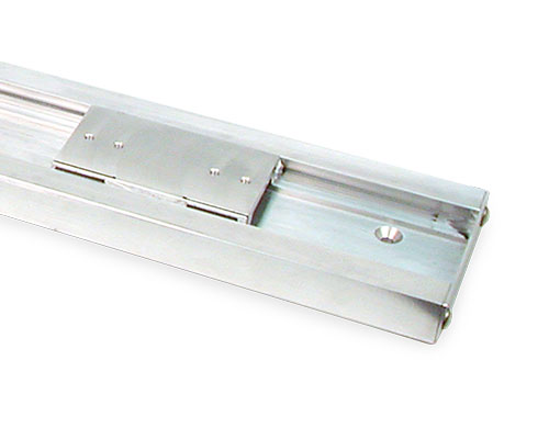
Free Sliding Model – The simplest UniSlide Assembly where the slider is moved by hand. This features a linear dovetail bearing for smooth motion. |
|
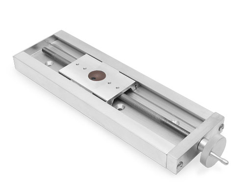
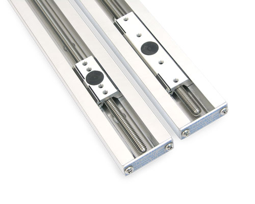
Screw Drive Models – Slide movement is controlled by a lead screw. There are a variety of different diameter lead screws available from 3/8" to 1/2" and 10 mm. Each have different advance ratings. |
|
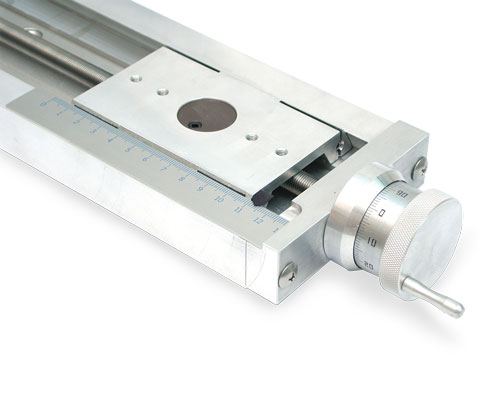
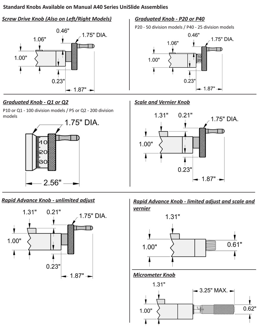
Graduated Knob Models – The position of the payload is measured by combining the readings from the linear scale and engraved knob or drum dial. Measures position from 0.001" or 0.01 mm. |
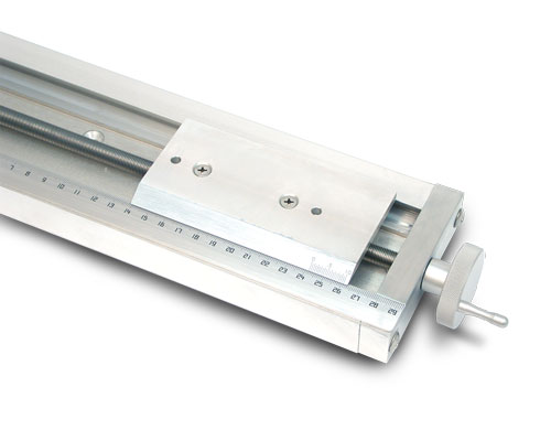 |
Scale and Vernier Screw Drive Models – Includes a precision English or Metric scale on the base and offset vernier on the slider. Measures position from 0.001" or 0.05 mm. |
Rapid Advance Models – Are for quickly repositioning the slider by uncoupling the drive system. This saves time when the slider will be moved frequently or when the base length is long. Each have varying lengths of fine adjustment. The limited fine adjust models use a clamping-like drive. The unlimited fine adjust models use a lead screw and pinion design. Rapid Advance models are not recommended for vertical (Z axis) mounting. |
|
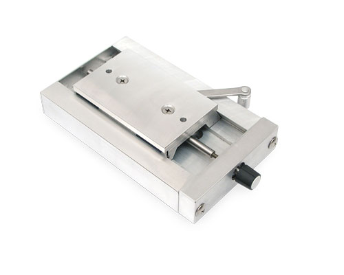 |
Rapid Advance with Limited Fine Adjust – Have 1/2" of fine pitch adjustment control. |
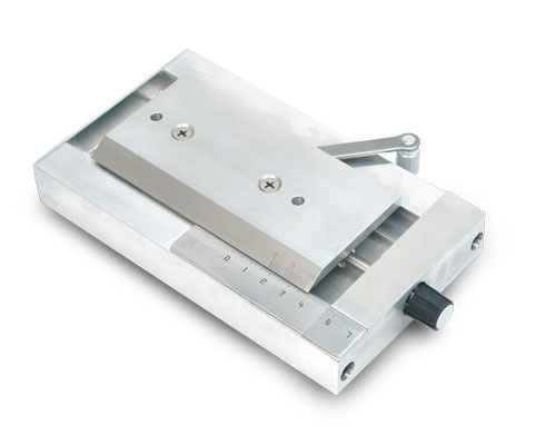 |
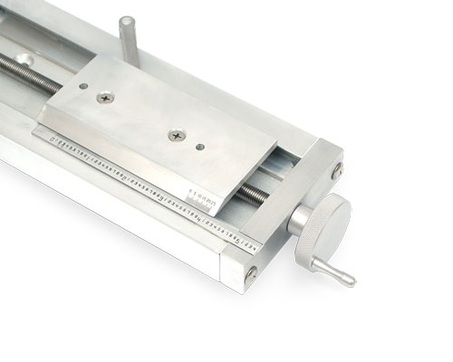
Rapid Advance with Limited Fine Adjust with Scale and Vernier – Limited fine adjust is also available with an English or Metric scale and vernier. |
 |
Rapid Advance with Unlimited Fine Adjust – Can be finely adjusted along the full length of the travel. Load is limited to 50 pounds horizontal or 2 pounds vertical. Configuration available on A25, A40 and A60 Series. |
 |
Rapid Advance with Unlimited Fine Adjust with Scale and Vernier – The unlimited fine adjust is also available with an English or Metric scale and vernier. |
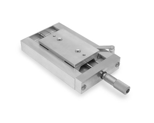 |
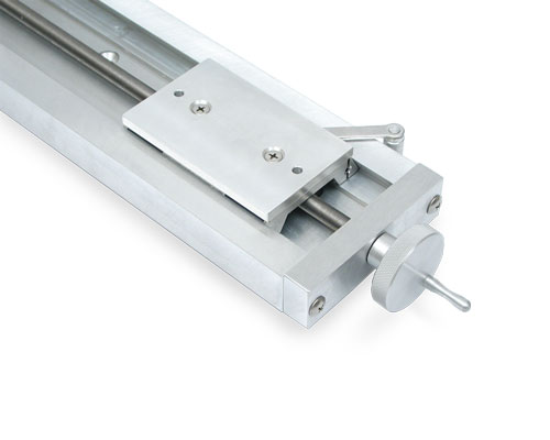
Rapid Advance with Micrometer Head – The limited fine adjustment is made with a micrometer calibrated to 0.001".(0.01 mm metric available as s special order. Contact Velmex.) Configuration available on A15, A25 and A40 Series. |
|
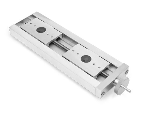
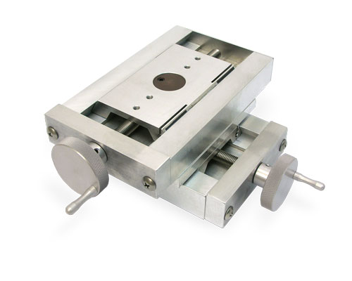
Left-Right Screw Drive Models – Use two carriages (sliders) and have a common lead screw machined with a left thread on one half and a right thread on the other half. The slides simultaneously move toward or away from each other. Use for applications where two objects must share a common axis of movement. Dual Screw models also available with two screws contolled independently with two knobs. |
There is a motorized version of the A40 Series UniSlide - MA40 Series. Other configurations and sizes are available on the other Series UniSlide Assemblies - A15, A25, A60, B90.
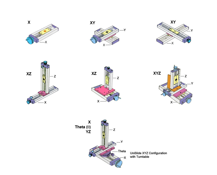
UniSlide Configurations
The basic linear UniSlide is a 1-axis stage. UniSlides can be combined for multiple axes in a wide range of lengths and payload capacities. See Examples for images of various multi-axis UniSlides and combinations that include other Velmex stages.
UniSlide® Specifications – Manually-Operated Assemblies
Factors such as size of the motor, size of the payload, travel distance, mounting direction/plane, etc. effect the actual capability of any assembly. Please contact Velmex Application Engineers to configure a system that will meet your exact requirements.
|
UniSlide® A40 Series | |
| Travel Distance‡ | 2" - 38" | 5.08 – 96.52 cm |
| Base Length | 6" - 42" | 15.24 – 106.68 cm |
| Slider Length | 4" | 10.16 cm |
| Weight | 2.4 – 11 lbs. | 1.1 – 5 kg. |
| Height** | 1.06" | 2.69 cm |
| Width | 4" | 10.16 cm |
| Maximum Horizontal Load | 100 lbs. | 45.5 kg. |
| Horizontal Central Load | 100 lbs. | 45.5 kg. |
| Cantilevered Load | 130 lb-in | 14.7 N-m |
| Vertical Central | 50 lbs. | 22.7 kg. |
| Load Normal (LN)* | 40 lbs. | 18.14 kg. |
| Load Thrust (LT)* | 20† lbs. | 9.07† kg. |
| Cantilever Side (LCS)* | 32 lb-in | 3.62 N-m |
| Cantilever Inline (LCI)* | 64 lb-in | 7.23 N-m |
* Normal Operating Loads are less than the maximum.
† 5 lbs max for Rapid Advance models (A40 & A60).
** Deeper "B" base configurations available.
‡ Standard travel distances available are in 3" increments.
Repeatability |
0.00015" (4 microns) typical |
Straight line accuracy |
Bow - 0.002" per foot; Run Out - 0.001" per foot; Twist - 1 milliradian per foot |
Screw lead accuracy |
Standard Lead Screw: 0.007"/10" Precision Lead Screw: 0.0015"/10" or better available. Consult factory. |
Operating temperature |
0 to 180° F (-18 to 82° C) |
| Properties of Velmex Stages | Information on stage composition, tolerances, wear and design for specialty applications. |
Lead Screws Available for A40 Series
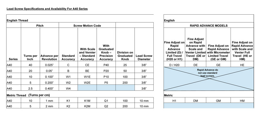
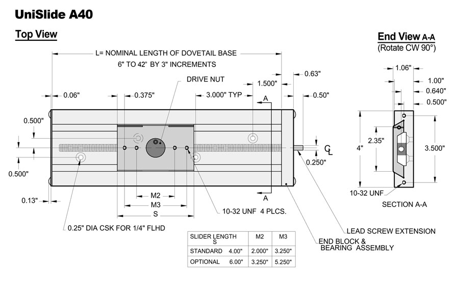
Basic Dimensions for A40 Series UniSlide Assemblies
Options/Accessories
An array of options and accessories is available for the A40 Series UniSlide Assemblies
Adapter Plates |
||
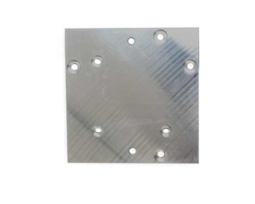
XY Plates – allow two UniSlides to be converted into an XY motion system. For more specifics and to see the adapter plates in use on a Velmex stage visit the UniSlide Adapters page. |
||
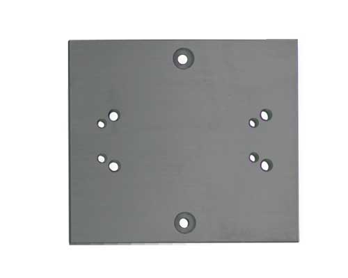 |
A4000XY Adapter Plate – To mount an A40 Series UniSlide to another A40 Series or to an A25 Series in XY. (The A40 would be the base stage.) |
|
 |
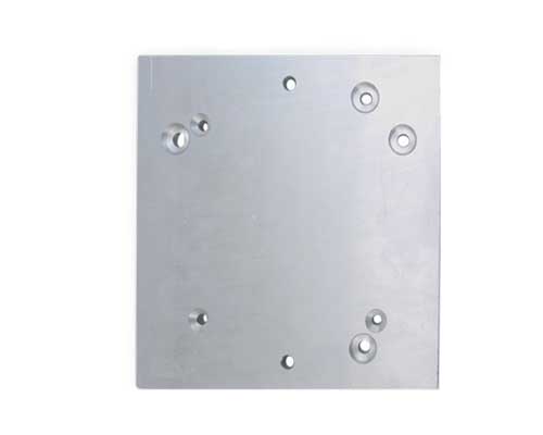
A6000XY Adapter Plate – To mount an A60 Series UniSlide to another A60 Series or to an A40 Series in XY. (The A60 would be the base stage.) |
|
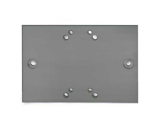
XZ Plates – Allow UniSlide assemblies to be positioned vertically facing in any of four directions. For more specifics and to see the adapter plates in use on a Velmex stage visit the UniSlide Adapters page. |
||
 |
A4000XZ Adapter Plate – To mount an A40 Series UniSlide or an A25 Series vertically to another A40 Series in XZ. (The A40 would be the base horizontal stage.) |
|
 |
A6000XZ Adapter Plate – To mount an A60 Series UniSlide to another A60 Series or to an A40 Series in XZ. (The A60 would be the base horizontal stage.) |
|
XZ Brackets – allow UniSlide assemblies to be positioned vertically, facing in any of four directions and perpendicular to the X or Y plane. For more specifics and to see the brackets in use on a Velmex stage visit the UniSlide Adapters page. |
||
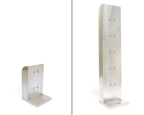 |
A4001XZ Adapter Bracket – To mount an A40 Series UniSlide (6"- 9") or an A25 Series (6"- 9") vertically to another A40 Series in XZ. (The A40 would be the upper horizontal stage.) Can also mount two B4800TS Rotary Tables at right angles. |
|
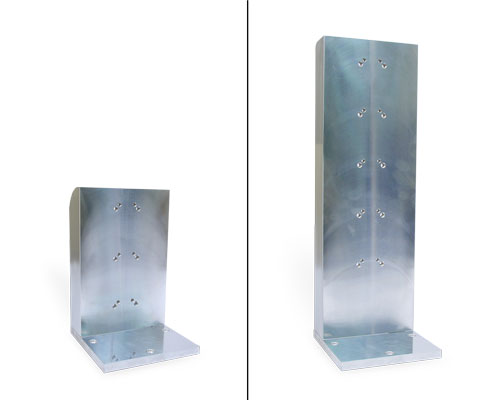 |
A6001XZ Adapter Bracket– To mount an A60 Series UniSlide to another A60 Series (up to 12") or to an A40 Series (up to 12") in XZ. (The A60 would be the base horizontal stage.) |
|
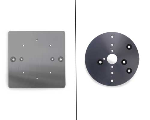 |
Rotary Table Adapter Plates –To mount Velmex Rotary Tables to UniSlide Assemblies either in horizontal or vertical positions. |
|
A6000TX Adapter Plate –To mount an A48 Series Rotary Table to an A40 Series or A60 Series UniSlide. (The UniSlide would be the base horizontal stage.) |
||
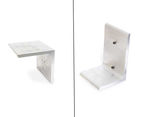 |
Platform Shelf – A right angled bracket designed to be used with UniSlide® Elevating Tables. However, they also can be used with vertically mounted UniSlide Assemblies to support a payload. The shelf can be inverted depending on the motion required. For more specifics and to see the shelf in use on a Velmex stage visit the UniSlide Adapters page. |
|
 |
Slider Lengths - Varying length carriages (sliders) can be added to all models of UniSlide Assemblies. Choosing a longer slider reduces the standard travel distance. 4" is the standard slider on the A40 Series. 6" is the optional length available for the A40. |
|
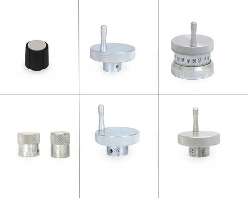 |
Alternative Knobs – A variety of knob styles can be substitute for the standard knob available on the particular style/model of UniSlide Assembly. |
|
• Small diameter (5/8") Rogan knob for some A15, A25, A40 Models and Turntables |
||
A40 Series Standard Knobs Available
Click to Open
|
||
Locks – There are a number ways to lock the carriage (slider) position on UniSlides. They include: |
||
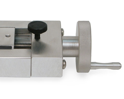 |
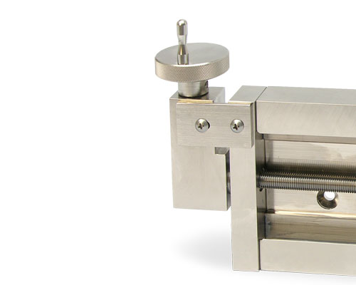
Thumbscrew-on-Lead-Screw Lock (-TL) – An easy method to fix the slider utilizing a simple thumbscrew. The thumbscrew lock increases the overall length of the UniSlide base. This lock type is not available on Rapid Advance models. |
|
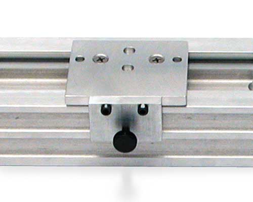 |
Traveling Slider Lock (-TSL) – This lock attaches to the slider to lock the carriage in place. Available on Free Sliding, Screw Motion and Graduated Knob models only. |
|
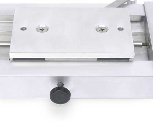 |
Slider Lock (-SLR or -SLL) – This lock is mounted at the mid-point on the base and is tightened to prevent slider movement. This is only available on slides where the carriage (slide) length is greater than one-half the base length. It can be mounted on the right (-SLR) or left (-SLL) of the base. |
|
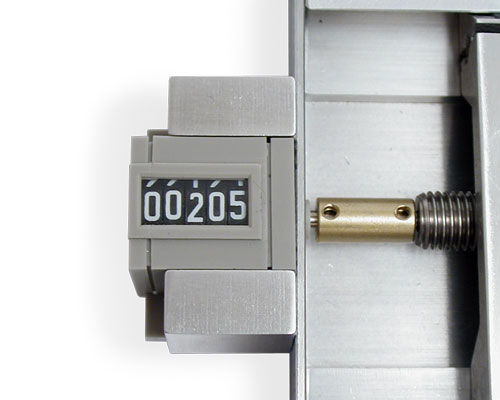 |
Revolution Counter (-RC) – A mechanical revolution counter provides a convenient 1/10 revolution increment count. Readouts in either 0.01" or 0.1 mm. Counts precisely with 0.100" or 1 mm lead screws. Other screws require additional calculations. For details see UniSlide Counter page. |
|
|
Left-Right Screw Motion (-LR) – This configuration is very useful for applications where two objects must share a common axis of movement. This assembly incorporates two carriages driven by a single right- and left-hand threaded lead screw. When the knob is turned, the carriages simultaneously move toward or away from each other. |
|
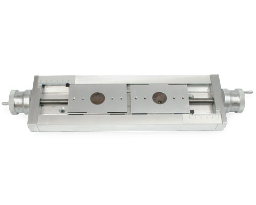 |
Two Independent Carriages (-DS) – a variation on the left-right screw motion UniSlide is one containing two lead screws with control knobs at both ends of the assembly. Each lead screw and carriage operates independently. |
|
 |
Right Angle Gearbox – Allows the control knob or wheel to be offset perpendicular to the UniSlide ways. Ideal for tight spaces or applications where access to the end of the stage is limited. Available on A25, A40, A60 and B90 Series. For more specifics on the gearbox visit the UniSlide Adapters page. |
|
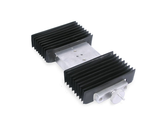 |
Way Covers (-WC) – Protect the slider and dovetail base from dust, dirt and grit that could hamper the efficient operation of the slide. Way covers increase slider height and reduce the travel length of linear UniSlide stages. Not available on Series A15 Assemblies. Available on free sliding, screw drive and graduated knob models of the other assemblies. |
|
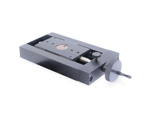 |
Finishes – Standard UniSlide Assemblies have a brushed aluminum finish. Optional finishes are available at an additional charge and include: |
|
• Black Anodizing, additional colors also available. (pictured) |
||
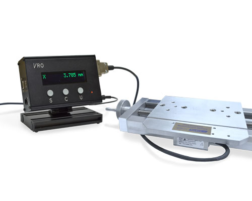 |
Encoders and VRO® Encoder Readout – For a high resolution position readout an encoder and Velmex's VRO encoder readout can be mounted to most linear UniSlide assemblies. An encoder, mounted directly to the slider gives a true and accurate reading eliminating lead screw and backlash errors. (Not available on all UniSlide models.) SEE: Velmex Controls on the Encoders and the VRO Readout for additional details. |
|
For .STP files, you may need to right click on the download button and save the "target" or "link".
Free Slides
| Series | Type | File Name | Description | Download | View |
|---|---|---|---|---|---|
| A40 | STP | A4006A-S4.stp | Free Slide, 2" Travel | - | |
| A40 | STP | A4009A-S4.stp | Free Slide, 5" Travel | - | |
| A40 | STP | A40012A-S4.stp | Free Slide, 8" Travel | - | |
| A40 | STP | A4015A-S4.stp | Free Slide, 11" Travel | - | |
| A40 | STP | A4018A-S4.stp | Free Slide, 14" Travel | - | |
| A40 | STP | A4021A-S4.stp | Free Slide, 17" Travel | - | |
| A40 | STP | A4024A-S4.stp | Free Slide, 20" Travel | - | |
| A40 | STP | A4027A-S4.stp | Free Slide, 23" Travel | - | |
| A40 | STP | A4030A-S4.stp | Free Slide, 26" Travel | - | |
| A40 | STP | A4033A-S4.stp | Free Slide, 29" Travel | - | |
| A40 | STP | A4036A-S4.stp | Free Slide, 32" Travel | - | |
| A40 | STP | A4039A-S4.stp | Free Slide, 35" Travel | - |
Lead Screw / Rapid Advance
| Series | Type | File Name | Description | Download | View |
|---|---|---|---|---|---|
| 2" Travel | |||||
| A40 | STP | A4006D-S4.stp | Rapid Advance - limited adj., 2" Travel | - | |
| A40 | STP | A4006Dx-S4_scale_vernier.stp | Rapid Advance - limited adj. with scale and vernier, 2" Travel | - | |
| A40 | STP | A4006Gx-S4_micrometer.stp | Rapid Advance - limited adj. with micrometer, 2" Travel | - | |
| A40 | STP | A4006HM-S4_scale_vernier.stp | Rapid Advance - unlimited adj. with scale and vernier, 2" Travel | - | |
| A40 | STP | A4006Hxx-S4.stp | Rapid Advance - unlimited adj., 2" Travel | - | |
| A40 | STP | A4006xxx-S4_scale_vernier.stp | Lead screw with scale and vernier, 2" Travel | - | |
| A40 | STP | A4006xx-S4.stp | Lead screw, basic knob and crank, 2" Travel | - | |
| A40 | STP | A4006xxx-S4_graduated_knob.stp | Lead screw, graduated knob, 2" Travel | - | |
| A40 | STP | A4006xx-S4-TL.stp | Lead screw, basic knob and crank, 2" Travel, thumb lock | - | |
| 5" Travel | |||||
| A40 | STP | A4009D-S4.stp | Rapid Advance - limited adj., 5" Travel | - | |
| A40 | STP | A4009Dx-S4_scale_vernier.stp | Rapid Advance - limited adj. with scale and vernier, 5" Travel | - | |
| A40 | STP | A4009Gx-S4_micrometer.stp | Rapid Advance - limited adj. with micrometer, 5" Travel | - | |
| A40 | STP | A4009HM-S4_scale_vernier.stp | Rapid Advance - unlimited adj. with scale and vernier, 5" Travel | - | |
| A40 | STP | A4009Hxx-S4.stp | Rapid Advance - unlimited adj., 5" Travel | - | |
| A40 | STP | A4009x-S4-LR.stp | Lead screw, basic knob, left / right model with dual carriages, Carriage separation 1" | - | |
| A40 | STP | A4009xxx-S4_scale_vernier.stp | Lead screw with scale and vernier, 5" Travel | - | |
| A40 | STP | A4009xx-S4.stp | Lead screw, basic knob and crank, 5" Travel | - | |
| A40 | STP | A4009xxx-S4_graduated_knob.stp | Lead screw, graduated knob, 5" Travel | - | |
| A40 | STP | A4009xx-S4-TL.stp | Lead screw, basic knob and crank, 5" Travel, thumb lock | - | |
| 8" Travel | |||||
| A40 | STP | A4012D-S4.stp | Rapid Advance - limited adj., 8" Travel | - | |
| A40 | STP | A4012Dx-S4_scale_vernier.stp | Rapid Advance - limited adj. with scale and vernier, 8" Travel | - | |
| A40 | STP | A4012Gx-S4_micrometer.stp | Rapid Advance - limited adj. with micrometer, 8" Travel | - | |
| A40 | STP | A4012HM-S4_scale_vernier.stp | Rapid Advance - unlimited adj. with scale and vernier, 8" Travel | - | |
| A40 | STP | A4012Hxx-S4.stp | Rapid Advance - unlimited adj., 8" Travel | - | |
| A40 | STP | A4012x-S4-LR.stp | Lead screw, basic knob and crank, 4" Carriage separation | - | |
| A40 | STP | A4012xxx-S4_scale_vernier.stp | Lead screw with scale and vernier, 8" Travel | - | |
| A40 | STP | A4012xx-S4.stp | Lead screw, basic knob and crank, 8" Travel | - | |
| A40 | STP | A4012xxx-S4_graduated_knob.stp | Lead screw, graduated knob, 8" Travel | - | |
| 11" Travel | |||||
| A40 | STP | A4015D-S4.stp | Rapid Advance - limited adj., 11" Travel | - | |
| A40 | STP | A4015Dx-S4_scale_vernier.stp | Rapid Advance - limited adj. with scale and vernier, 11" Travel | - | |
| A40 | STP | A4015Gx-S4_micrometer.stp | Rapid Advance - limited adj. with micrometer, 11" Travel | - | |
| A40 | STP | A4015HM-S4_scale_vernier.stp | Rapid Advance - unlimited adj. with scale and vernier, 11" Travel | - | |
| A40 | STP | A4015Hxx-S4.stp | Rapid Advance - unlimited adj., 11" Travel | - | |
| A40 | STP | A4015xxx-S4_scale_vernier.stp | Lead screw with scale and vernier, 11" Travel | - | |
| A40 | STP | A4015x-S4-LR.stp | Lead screw, basic knob and crank, 7" Carriage separation | - | |
| A40 | STP | A4015xx-S4.stp | Lead screw, basic knob and crank, 11" Travel | - | |
| A40 | STP | A4015xxx-S4_graduated_knob.stp | Lead screw, graduated knob, 11" Travel | - | |
| 14" Travel | |||||
| A40 | STP | A4018Hxx-S4.stp | Rapid Advance - unlimited adj., 14" Travel | - | |
| A40 | STP | A4018xxx-S4_scale_vernier.stp | Lead screw with scale and venier,, 14" Travel | - | |
| A40 | STP | A4018x-S4-LR.stp | Lead screw, basic knob and crank, 10" Carriage separation | - | |
| A40 | STP | A4018xx-S4.stp | Lead screw, basic knob and crank, 14" Travel | - | |
| A40 | STP | A4018xxx-S4_graduated_knob.stp | Lead screw, graduated knob, 14" Travel | - | |
| 17" Travel | |||||
| A40 | STP | A4021Hxx-S4.stp | Rapid Advance - unlimited adj., 17" Travel | - | |
| A40 | STP | A4021x-S4-LR.stp | Lead screw, basic knob and crank, 13" Carriage separation | - | |
| A40 | STP | A4021xx-S4.stp | Lead screw, basic knob and crank, 17" Travel | - | |
| A40 | STP | A4021xxx-S4_graduated_knob.stp | Lead screw, graduated knob, 17" Travel | - | |
| 20" Travel | |||||
| A40 | STP | A4024Hxx-S4.stp | Rapid Advance - unlimited adj., 20" Travel | - | |
| A40 | STP | A4024x-S4-LR.stp | Lead screw, basic knob and crank, 16" Carriage separation | - | |
| A40 | STP | A4024xx-S4.stp | Lead screw, basic knob and crank, 20" Travel | - | |
| A40 | STP | A4024xxx-S4_graduated_knob.stp | Lead screw, graduated knob, 20" Travel | - | |
| 23" Travel | |||||
| A40 | STP | A4027xx-S4.stp | Lead screw, basic knob and crank, 23" Travel | - | |
| A40 | STP | A4027xxx-S4_graduated_knob.stp | Lead screw, graduated knob, 23" Travel | - | |
| 26" Travel | |||||
| A40 | STP | A4030xx-S4.stp | Lead screw, basic knob and crank, 26" Travel | - | |
| A40 | STP | A4030xxx-S4_graduated_knob.stp | Lead screw, graduated knob, 26" Travel | - | |
| 29" Travel | |||||
| A40 | STP | A4033xx-S4.stp | Lead screw, basic knob and crank, 29" Travel | - | |
| 32" Travel | |||||
| A40 | STP | A4036xx-S4.stp | Lead screw, basic knob and crank, 32" Travel | - | |
| A40 | STP | A4039xx-S4.stp | Lead screw, basic knob and crank, 32" Travel | - | |